Download
1 / 67
670 likes | 804 Vues
This report examines the issue of skyglow in rural areas of the UK, highlighting the alarming rise in ambient lighting from 1993 to 2000. It explores various rural luminance profiles, illuminance modeling, and examines the impact of unshielded lighting. The study dispels common myths around skyglow causation, advocating for better lighting practices such as full cut-off luminaires. The report emphasizes the urgent need for legislation to mitigate light pollution and preserve the visibility of the night sky, ensuring a future where both nature and astronomy can thrive.

E N D
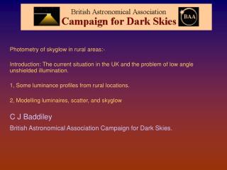
Measuring and Modelling Rural skyglow Photometry of skyglow in rural areas:- Introduction: The current situation in the UK and the problem of low angle unshielded illumination. 1, Some luminance profiles from rural locations. 2, Modelling luminaires, scatter, and skyglow C J Baddiley British Astronomical Association Campaign for Dark Skies.
NOAA CPRE UK changes Map NOAA UK isophotic data for 1993 and 2000 Black 0-1.7 ..can see MW when clear, Blue 1.7-50 MW visible occasionally, light blue 50-150 can see MW very occasionally, yellow 150-240.. And above ..never see the Milky Way, Red... instrument saturation 24-255. The increase in the ambient lighting at the second isophot level in just 7 years is alarming. (NOAA/ CPRE) NOAA data UK light pollution increase from 1993 to 2000
Europe prediction from DMSP data Atmospheric light pollution Europe now and prediction for 2025 Computer modelled atmospheric skyglow isophotes for Europe, Left 1995. Right prediction for 2025 From a few stars only visible (red) to a few hundred (yellow to green), to near a thousand , some Milky Way visibility, to dark sky (black). Based on DMSP nadir data . (Cinzano P., Falchi F., Elvidge C.D., Baugh K.)
Highways agency Highways Agency. Responsible for major roads and Motor Ways. HA has long since adopted Full Cut-off lighting on all new Motor Ways, Also found now on new roundabouts in open areas. NATA environmental impact appraisal. New Approach To Appraisal - a high priority for the effect of the environmental impact of lamps when choosing them. Is it working ? Rural roundabout at Beckington, Somerset, on the A36 between Bath & Warminster. before then re-lit with HCO lights (John Ball)
ILE Zones light levels Luminaires and installation information
2003 The Science and Technology Committee inquiry into light pollution and astronomy. A lot of CFDS input written and aural evidence. • Many recommendations, Central recommendation .. That there should be legislation against stray lighting. • On 2004 Feb 12th There was a Parliamentary debate on the report and its findings, at Westminster Hall. UK parliament S&T ctte and Gov initiatives • A discussion in the House of Lords was held in mid June. ‘The Government is working on the issue at the speed of light’ (!) • ODPM to produce an annex to PPS23, obliging councils to control external lighting through planning requirements. • Re. PPS23, Discussions are being held at the Office of the Deputy Minister between stakeholders and Government departments. Inc. ILE, RAS, and CfDS. • DEFRA intention to make lighting intrusion a statutory nuisance.
Measuring rural skyglow Photometry of skyglow :- 1, Some luminance profiles from rural locations. C J Baddiley Images by James Weightman, Mike Tabb and Bob Mizon
Summary of finding dispelling myths Sky-glow in rural areas, under atmospheric conditions where stars might be visible.Dispelling assumptions and myths……. • Sky glow is due to light sent directly upwards. No, it is not. • It is also due to reflected light straight up into the sky. No, it is not. • In order to control it we need to cut-out all directly upward light. No, we do not. • When we see skyglow on the horizon from a town, it is from the sky just above the town. No, it is not. • The reflected light is mostly from road surfaces. No, it is not. • It doesn't matter what sort of luminaire is used, scattering in the atmosphere guarantees it ends up as sky glow. Not true. • Switching to white light will reduce sky glow because such luminaries can be run at scotopically matched lower intensity levels. Not necessarily. • Shallow bowl lights luminaires cause less sky glow than fuller cut-off types, because less of them are needed per given road length. No, not convincingly.
Elevated view of LA Los Angeles in 1988 (IDA). Individual light sources dominate this scene, and the illumination of the sky behind the viewer
Elevated view of Belfast Belfast form an elevated location (Peter Paice).
Elevated view of Worcester Worcester (12 Km away) with its skyglow, the M5 motorway across the Severn valley looking East, south of Worcester, from the Malvern Hills. (Chris Baddiley) What you see is direct light from many luminaires, right to the far side of Worcester. That is what is illuminating the sky and clouds behind the viewer in the same sight line in rural Herefordshire. All this is wasted light from just above the horizontal.
Direct and reflected rays diagram Air molecules Reflected Skyglow is caused by the downward scattering of upward light by air molecules and also aerosols, mostly water droplets and dust. The longer the path length through the lowest part of the atmosphere, the more the scattering. Light that goes straight up is mostly reflected, and has shorter paths through the lower scattering layers. The low angle light is mostly directly radiated, and it is this that causes most of the sky glow well away from the source. Aerosols Radiated.
Visibility limit, star light and skyglow tables A table of stellar magnitude, number of stars per square degree that are visible to those limits and the total number of visible stars sky and total illuminance. Compared with sky glow figures in the lower table. Birmingham sky is about magnitude 17 per square arc second, which is magnitude -1 per square degree and for the whole sky is 57 millilux on the ground. Darkest Holland is magnitude 20 per square arc second and that is 3.6 millilux. Sky glow is still exceeding the total starlight. In Birmingham it exceeds it by factor of 20.
Visibility limit map for Cotswolds Dark sky areas of the Cotswolds (P. Cinzano - Dipartimento di Astronomia Padova, Italy), Philips – Maps publication for CfDS. Commercial publication, 2004 September
Illuminated cloud base Cotswolds 2003/8/20 at location SO967102 looking south (main glow Swindon 30+ Km SSE); Mars visible left. Sagittarius right. Illumination of clouds from underneath Canon D60 digital SLR + 15mm f/2.8 lens. ISO 800 15 secs. (James Weightman)
Skyglow in the Cotswolds Skyglow in Cotswolds, location SO967102. Western quadrant, composite transformed to equal area projection, CCD image images (James Weightman) Milky Way, Scutum, Sagittarius etc taken last night 2003/8/2 at SO967102 near Cirencester, Glos; Unguided Olympus C5050Z Skyglow in Cotswolds, location SO967102. Western quadrant, composite transformed to equal area projection, CCD image images (James Weightman) Milky Way, Scutum, Sagittarius etc taken last night 2003/8/2 at SO967102 near Cirencester, Glos; Unguided Olympus C5050Z Even in the countryside, there is no escape ! Note the gradation from the horizon upwards, due to the concentration of scattering aerosols at lower altitudes. The skyglow from very distant sources is still bight.
Analysis picture Skyglow in the Cotswolds CCD composite of 20 x15 second exposures. Cotswold Hills, 6 miles south of Cheltenham. It can be seen, perhaps aided by the rising early morning mist, that a glow can be seen all around the horizon, particularly at 12 o' clock. Location SO967102 (Cheltenham), 7 o'clock (Cirencester). By James Weightman, BAA Made from 12 images covering the whole sky taken with wide angle zoom 7 mm fl lens, setting of Casio QV3500 digital camera over a period of approx 15 minutes.
Cotswolds Weightman image, photometry Intensity profiles of horizon to zenith lines as shown. The towns are from the top 12 o'clock Cheltenham, 7 o'clock Cirencester.
Cotswolds Weightman image, analysis The apparent elevations of identified stars is compared with true elevations and corrected Sky brightness Mag 18.5 /sq arcsec at Polaris.
Cotswolds, Mike Tabb image Sky glow in the countryside, from distant towns from the darkest Cotswolds. The lens compresses objects to the horizon (see the tree), so the dark hole overhead appears actually smaller than shown. Location ST829 743 (Mike Tabb). The towns, are clockwise from the top, Leigh Delamere, Bristol, Bath, Trowbridge, Melksham, Chippenham, Swindon
Cotswolds, photometryMike Tabb image Intensity profiles of horizon to zenith lines as shown. The towns, are clockwise from the top, Leigh Delamere, Bristol, Bath, Trowbridge, Melksham, Chippenham, Swindon
Visibility limit map for Dorset Skyglow maps of the areas of the Darkest Hampshire and Dorset, The New Forest (National Park) (P. Cinzano - Dipartimento di Astronomia Padova, Italy), Philips – Maps publication for CfDS. Commercial publication, 2004 September
Poole, and ferry terminal Bob Mizon image Sky glow from Poole
Poole photometry Intensity profiles of horizon to zenith lines as shown. The curves fit well, despite this being a limited field of view in which has a (Cos angle from the centre )^3 sensitivity law , and the gamma of the film is unknown.
Rural skyglow estimation summary Sky brightness lower limit estimates Cotswolds Weightman data Mag 18.6 /sq arcsec at 52 deg elevation. Cotswolds Tabb data Mag 18.2 /sq arcsec at 52 deg elevation. Poole Mizon data Mag 18.2 /sq arcsec at 30 deg elevation.
Modelling luminaires and skyglow Photometry of skyglow :- 2, Modelling luminaires, scatter, and skyglow C J Baddiley
Luminaire distributions Luminaire polar distributions and ground reflections
Luminaires polar plot gamma for c=90/180 Luminaire light distribution profile for a SOX luminaire (deep orange), shallow bowl (light orange) and a full horizontal cutoff light (pink) of the same total luminosity
Luminaires polar plot gamma and C Skyglow modelling Luminaire light distribution profile for a SOX, (deep orange), shallow bowl (light orange) and a full horizontal cutoff light (pink) of the same total luminosity Note the radiance at horizontal in azimuth of the LPS SOX luminaire shows its self-obscuration. 27% upward light ratio.
Skyglow modelling Direct and surface reflected rays diagram Direct view radiated. At shallow angles there is a reflected component that is enhanced by the increased reflectivity of with incidence angle. Surfaces near grazing incidence are blocked by hedges, buildings terrain etc.There is also the direct upward component. Reflected Same view angle reflected All direct light above horizontal not blocked. Reflectivities: at 589 nm wavelength Soil 0.1 Grass 0.08 Foliage 0.06 Asphalt 0.04to 0.08 (dirty) Concrete 0.25 Shallow angle reflected light blocked.
Surface reflectivity vs angle Reflectivity as a function of angle of incidence to normal. Reflectivites of surfaces increase towards grazing incidence. Smooth surfaces go to unity. The Brewster angle is before this which blocks the horizontally polarised components. Most surfaces, even roughness are very reflective beyond 70 degrees, i.e. below 20 degrees to the horizontal. Low angel light is reflected, smooth ones become a mirror. Grass reflectivity 0.1 Rises to 0.2 at 80 degrees, asphalt goes from 0.04 to 1 at grazing angle, as does water
Surface reflectivity spectrum Reflectivities vary with wavelength. Grass is less reflective in yellow. Switching to white light increases its value. The minimum reflectivity is at about 670 nm where light is absorbed by photosynthesis, in common with all vegetation. Reflectivities rise rapidly in the near infrared for thermal rejection. Reflectivities: at 589 nm wavelength Soil 0.1 Grass 0.08 Foliage 0.06 Asphalt 0.04to 0.08 (dirty) Concrete 0.25
Luminaires reflection and upper radiance polar plot gamma for c=90/180 Luminaire light distribution profile showing downward and sideways direct component and reflected components profile for a LPS SOX (deep orange), shallow bowl HPS SON (light orange) and a HPS SON full horizontal cutoff light (pink) of the same total luminosity Elevation at azimuth 0/180,
Luminaires reflection and upper radiance polar plot gamma for c Skyglow modelling Luminaire light distribution profile showing downward and sideways direct component and reflected component, lumaires as before. Top line elevation view for orthogonal azimuths, bottom line horizontal azimuthal plot left and same but at 110 nadir, (20 degs above horizontal) right. Elevation at azimuth 0/180, Elevation at azimuth 90/270, Azimuth plot at horizontal Azimuth plot 5 deg above horiz. Azimuth plot 20 deg above horiz.
SOX LPS SOX reflection and upper radiance polar plot gamma for c Skyglow modelling Radiated (orange), reflected (green), total (red) This frame shows the polar plot for the reflected and direct upward radiation in the vertical plane along the road, for the three light types previously described. The low pressure sodium SOX light source has a dominant direct radiated component which exceeds the reflective component at low angles to the horizontal. Reflected components have been blocked below 15° above horizontal as previously described Elevation at azimuth 0/180, Elevation at azimuth 90/270, Azimuth plot 5 deg above horiz. Azimuth plot 20 deg above horiz.
Shallow bowl reflection and upper radiance polar plot gamma and C Shallow bowl SON Skyglow modelling Radiated (orange), reflected (green), total (red) The SON cases above the horizontal are all reflective. The reflection pattern is nearly a mirror image of the ground luminance distribution, convolved with the scatter distribution on the ground surface. The asymmetry in the across road reflection is due to the rd and verge boundary. SOX LPS Elevation at azimuth 0/180, Elevation at azimuth 90/270, Azimuth plot 5 deg above horiz. Azimuth plot 20 deg above horiz.
HCO reflection and upper radiance polar plot gamma and C Skyglow modelling HCO SON The asymmetry in the across road reflection is due to the rd and verge boundary. Radiated (orange), reflected (green), total (red) Elevation at azimuth 0/180, Elevation at azimuth 90/270, Azimuth plot 5 deg above horiz. Azimuth plot 20 deg above horiz.
Integrated luminance tables Luminance integrated over a sphere, and upper hemisphere, direct, reflected and both, without and with obstacle blocking of reflected rays below 15 degree elevation. Note both the direct upward figures are high for the SOX luminaire. The SOX reflection value is most reduced by the 15 degree elevation obstacle blocking due to its wider spread on the ground compared with the others.
Atmospheric scattering Atmospheric scattering
Atmospheric scattering pictures Blue haze Rayleigh scattering by particles smaller then the wavelength of light Daylight Rayleigh scattering by air molecules, smaller than the wavelength of light. Equal forward and backward scatter, also sideways, Varies as 1 / wavelength 4 Mie scattering by aerosols.. water droplets and dust, similar or larger than the wavelength of light. No wavelength dependence and very directional.
Sky scatter from Sun (sun omitted) with elevation Rayleigh scatter air moleculesMie scatter from aerosolsTotal Scatter Sunset scatterring simulation Sun Elev. 5 o 0 o -2.5 o -5 o -10 o This is a sequence of a simulated sunset. The Sun has been removed from this picture, just showing the light scatter.
Scatter density with altitude The next plot shows the variation of density of air molecules and aerosols, as a function of altitude in the atmosphere. At 10 km altitude the density off the air has reduced to 2/3 of its ground value. The equivalent height of the total atmosphere brought to constant density is only a few Km.
Molecular scatter probability scatter probability for scatter angle (phase function). Rayleigh scattering.Light is coming in from below and being scattered in the direction of the grid angles. The curve gives the probability of scatter in that direction.Equal probability forwards and backwards, 50% of that sideways. The probability over all angles =1It varies in intensity as wavelength ^4 (blue biased). It is why the sky is blue by day
Aerosol Mie scatter probability Aerosol scatter probability for scatter angle (phase) functions (Mie scattering) (Heye-Greenstein function with added back scatter). The forward scatter is very peaked, increasing with particle size from 1nm to 10 microns The lower scatter probability profile is the one used. There is practically no sideways scatter and back scatter is tiny. No wavelength dependence, it is why clouds are white Dependence on particle size
Incremental and cumulative scatter What is scattered out of the beam is replaced by what is scattered into the beam. They have to be the same over the path length. So 1 - the negative exponential is the scattering into path. The proportion of light scattered out of the beam is proportional to the length of the increment. (proportional constant k) The input of the next increment is the output of the previous one. This is the starting differential equation that has the solution of an exponential accumulated scatter with distance.
Path geometry Path geometry Geometry
= elevation Re= Earth radius h = height of point z = total slant path k = scattering coefficient Km-1 Path geometry z h The path distance x is replaced with a function of elevation. The hypotenuse of the triangle shown. Maximum path length are at the lowest elevation. The negative exponential of (k x path length) is then taken, but the path density decreases with height
’ r Curved Earth geometry r’ h ’ s’ s d ’ d’ g g’ Re t Curved Earth geometry Re Re ’ q
Results Result plots … Incremental vs. distance along a given elevation path Total for vs. elevation at a given distance Total for a given elevation vs. distance Photometry of skyglow
Skyglow at high elevations. All large scatter angles, very few molecules up here Air molecules scattering at these large angles Skyglow at high elevations. As all scatter is at large angles it is mostly by air molecules, maximally in the blue. Little is from the upper parts of the path, as there the scattering is near orthogonal and the aerosol density is much lower. Ground reflection All large scatter angles Aerosols here but don’t scatter at much at these high angles, only direct radiation View elevation source angle Direct radiance (SOX)