Download
1 / 6
60 likes | 154 Vues
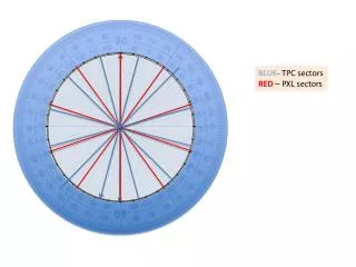
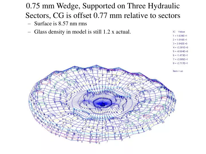
0.75 mm Wedge, Supported on Three Hydraulic Sectors, CG is offset 0.77 mm relative to sectors. Surface is 8.57 nm rms Glass density in model is still 1.2 x actual. Zernike Coefficients, nano-meters. Astigmatism. Power. Coma. Spherical. Geometry of the wedged mirror (100 mm thick).

E N D
0.75 mm Wedge, Supported on Three Hydraulic Sectors, CG is offset 0.77 mm relative to sectors • Surface is 8.57 nm rms • Glass density in model is still 1.2 x actual.
Zernike Coefficients, nano-meters Astigmatism Power Coma Spherical
Geometry of the wedged mirror (100 mm thick) Thickest point Sector Boundary FEM node number Actuators
Lateral Load, 6 Tangent Supports • Tangent supports in CG plane, optimized axial forces: • 15.34 nm rms surface • Tangent supports in 0.16” forward of CG plane (1.25” above back), optimized axial forces: • 13.23 nm rms surface
Lateral Support Without Correction • Three Tangent Supports: • 1 g Lateral …. 219 nm rms • Six Tangent Supports: • 1 g Lateral …. 59 nm rms • Strap Support • 1 g Lateral ….. 47 nm rms
Correction of Low Order Components • The magnitude of low order terms that can be corrected by 15 N maximum forces. • Procedure used: • Assume a 1 wave Zernike shape (coefficient = 1 wave). • Calculated optimum correction forces. • Scale from maximum optimum correction force to find shape coefficient that can be corrected with a 15 N force limit. • Residual is the surface distortion left after the Zernike shape is corrected. For example 0.05 waves of spherical can be corrected by a set of forces not exceeding 15 N to leave 0.4 nm-rms surface distortion. These are the data used to derive the results above.