Disk Sectors
This overview discusses the design history, requirements, and dimensional measurements of disk sectors for a high-precision system. It covers different sector designs and the challenges in meeting stability and dimensional requirements.

Disk Sectors
E N D
Presentation Transcript
Disk Sectors M. G. D. Gilchriese Lawrence Berkeley National Laboratory April 2000
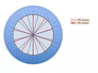
Overview 11-sector disk • Quantities • Six 11-sector disks. All sectors within these are identical for total of 66 sectors. • Four 9-sector disks. All sectors within these are identical, but not the same as 11-sector disk, for total of 36 sectors. • Total of 66+36=102 sectors required + additional for production losses, etc. • Reasons for different disk sizes • Saves $$ overall because pixel module costs outweigh cost of additional tooling. • More room for services 9-sector disk
Sectors->Rings->Disks • Focus in this talk on sectors. Eric will cover system integration.
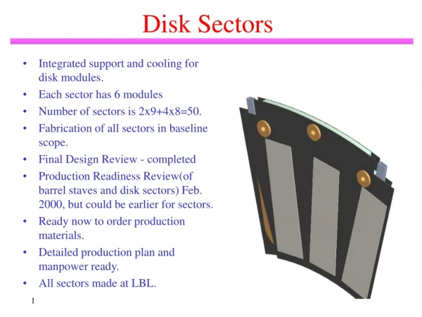
Baseline Sector Concept • Combined structural support with cooling. • Carbon-carbon faceplates. Front and back faceplates offset in phi to provide full coverage(no gaps). • Aluminum coolant tube between faceplates. • Three precision support points to disk ring. • Modules mounted on both sides.
Design History - Three Parallel Developments • All designs use carbon-carbon faceplates and differ only in coolant tube. • All-carbon design with Energy Sciences Laboratory, Inc(SBIR supported) • Glassy-carbon tube connected to faceplate by high-thermal-conductivity fibers • Status: Was baseline but rejected Dec. 99. Why? Insufficient time for redesign cycle for possible high pressure(coolant) fault conditions, poor vendor performance and expected higher cost. • All-carbon design with Hytec, Inc(SBIR supported) • Resin-sealed carbon-carbon tubes hard bonded to faceplates. • Status: development near completion. Possible “fall forward” option to replace current baseline. Cost comparable to baseline. Construction techniques and responsibilities similar to baseline. Will describe briefly and more in notes section of book. • Aluminum-tube design at LBNL • Rectangular aluminum tube soft bonded to faceplates. Carbon foam bonded between faceplates to provide stiffness. • Status: current baseline. Will describe in some detail and you will see parts during visit this afternoon.
Requirements and Design • Will walk through most of the requirements and the current status of the design/measurements. • Have arbitrarily classified the requirements into two types: hard and soft. Hard means must meet. Soft means there is still some uncertainty. • As you will see, we do not have data that convince us we can meet all requirements. Conversely so far so good - we simply need more data. • More work is needed, and since we changed the baseline design relatively recently we are not as advanced in all respects as we would like. • Will describe planning to address outstanding critical issues.
Stability Requirements • The stability requirements are the most difficult to define in terms of strict mechanical requirements. • The intrinsic precision in f is 12 microns and about 100 microns in Z or R(75 microns innermost barrel layer in Z). • The ultimate alignment of the system will be done using particle tracks, and there are lots of them. In principle, one could align regularly each module in the system using tracks(very, very crudely there are 50,000 tracks/module per day average at full luminosity). • In these terms, the requirement is to be stable to <10 microns rms in f and <50 microns in R(in the disks) over a period long enough to align with tracks. In the disks motion in Z couples to the other two coordinates. • Practically, the mechanical/cooling structure is designed to be as stable as possible and meet other constraints, particularly material. • The alignment hierarchy is first disks, then sectors then modules(in the disk region), so it’s desirable that disks and sectors be stable as possible under the combined effects of temperature change, coolant flow, moisture changes and power on/off. • In the end, judgement has to be used to evaluate the tradeoffs between meeting other requirements(material and cost/schedule) and stability.
Al-Tube Prototype History • All recent Al-tube prototypes have • Carbon-carbon facings • Reticulated vitreous carbon(RVC) foam bonded to the carbon-carbon facings • Aluminum tube bonded to facings with very low modulus, high thermal conductivity material(AI Technologies CGL7018)
Dimensional Requirements • Not enough prototypes have been built to provide a significant measurement of ability to meet dimensional requirements, but measurements on few prototypes show tolerances can be met. • Requirements are relatively relaxed because • the location in x,y and z of every module mounted on a sector will be measured after placement on a sector. There are targets on the silicon detectors in the module that are referenced to the pixel location to a few microns and we can measure the location of these targets relative to the mounting holes in the sector to better than 2 microns(rms in x or y) and 5 microns rms in z using optical CMM. • In addition, we plan to survey in x,y and z location of disk sectors relative to disk mounting points after assembly on disk ring. • QC/QA will include thickness measurements, measurements or go/no go templates for transverse dimensions, in addition to survey.
Thermal Requirements • The essential thermal requirement is to keep the silicon detector temperature less than or equal to -6oC for the worst case power load of 50W per sector. • The silicon detector temperature is determined by the coolant temperature, the temperature drop from the coolant to the face of the sector and the drop from the face through the attachment material and integrated circuit electronics. • Our current requirements on DTsare • Coolant to face of sector:<15oC(worst spot) with uniformity <5oC • Face of sector to detector: <4oC • Thus maximum DTtotal of <19oC • Which implies coolant temperature requirement of less than or equal to -25oC. We believe this is conservative(for sectors) and may be able to relax to allow warmer coolant but need more data. • Thermal requirement to be met after thermal cycling, pressure cycling, radiation and fault conditions.
Thermal Measurements • Heaters are attached to sectors to simulate heat loads. • IR camera measurements backed up by single point measurements with RTDs • Measurements have been done with water, water/methanol, liquid fluorocarbons and evaporative fluorocarbons. • Based on these measurements, we currently believe simple measurements of DTswith water are adequate for QC/QA but see critical items later. Platinum on silicon heaters to simulate heat loads. These are attached using the current baseline thermal material CGL7018. RTDs are also mounted to measure temperature at points and compare with IR images.
Prototype 6(5’) - 50Watts Water coolant at 11oC and 10cc/s. Maximum DTtotal about 10oC. Measured after pressure cycling 140 times up to 5 bar absolute and few cycles up to 7 bar absolute of sector without heaters attached.
Prototype 6(5’) - 60Watts Water coolant at 11oC and 20cc/s. Maximum DTtotal about 10oC. Measured after pressure cycling 140 times up to 5 bar absolute and few cycles up to 7 bar absolute of sector without heaters attached.
Thermal Performance - Pressure Cycling Before After 60 Watts. Water coolant at 11oC and 20cc/s. Maximum DTtotal about 14oC Sector pressure cycled from atmospheric to 5 bar absolute 24 times(for stability measurements - see later - and then heaters attached. Cycled with heaters attached 20 times to 3.7 bar absolute. No significant change in thermal performance measured. Prototype #4.
Thermal Performance - Irradiation Before After 36 Watts. Water coolant at 23oC and 15-17cc/s. Maximum DTtotal about 7oC Irradiate with Cobalt 60 source at LBNL over some months to 22 Mrad. No significant change in thermal performance measured. Prototype #3.
Thermal Performance - Evaporative Cooling • Verified with very early prototypes that evaporative cooling(although with C4F10 at that time) works with wiggly tube in all sector orientations. Additional tests with wiggly pipes have been done for silicon strip cooling system(which is also evaporative). • Tests were performed successfully on ESLI sector(again with C4F10 ) up to about 50W but stability at this power was marginal. • Calculations were done to compare with these measurements and to estimate the required hydraulic diameter for conservative operation to provide the required cooling. These calculations indicated that a hydraulic diameter of 3.3 mm would be required. For reference, prototype sector 6(5’) has a hydraulic diameter of 2.4 mm. • No measurements with evaporative cooling have been done on Al-tube sectors or with C3F8 with any sectors! • We have in place plan to build multiple sectors to test. Preliminary schedule will be discussed this week and is included for reference. • Two to run in series(as is baseline plan) with hydraulic diameter 2.4 mm • Two to run in series with hydraulic diameter of 3.3 mm • This will allow direct comparison. Choice of hydraulic diameter affects radiation length of sector - see later.
Thermal Performance - Conclusions • Measurements on three generations of prototypes indicate that basic thermal requirements can be met, possibly with significant headroom in overall DT. • Very preliminary results indicate that pressure cycling, normal operating pressure and irradiation requirements probably can be met. • Single fault failures(10 bar and loss of coolant) and performance after 50MRad not measured. • Critical issues • Need more statistics, more coherent measurements across multiple prototypes of same design - fabrication in progress. • Thermal performance of Al-tube sector with baseline evaporative cooling not measured but plan in place to do so. • QC/QA of bare sector is open issue. How do we tell if sectors have adequate thermal performance before mounting modules? We have scheme to mount temporary heaters(both sides) and measure with IR camera but far from proven.
Stability • We have made measurements of static deflections(out-of-plane) under temperature and pressure changes. • This has been done using TV holography(intrinsic resolution about 0.25 microns), optical CMM at LBL(intrinsic resolution <5 microns and direct measurements(dial indicators with intrinsic resolution <5 microns). • In addition, have made dynamic measurements of relative motion vs frequency using TV holography. • Stability measurement when mounted on disk support ring covered in next section of this talk - focus on single sector here.
Stability - Thermal Change • Measurements of out-of-plane deflection made on prototype #4(below) without coolant flow(cold box). Results for 40oC temperature change are given below for many points on sector.Worst points are wings. This is acceptable but would like to improve. • Temperature change distortion of prototype #3 was measured before and after 22 Mrad and found to be the same within errors.
Stability - Pressure Changes • Prototype 6(5’) out-of-plane motions measured at each point indicated. • Data taken up to about 5 bar absolute, then was cycled 140 times to 5 bar absolute and then data taken up to 7 bar absolute. • Body distortions maximum of 15 microns, typically few microns. • Distortions on “wings” more, up to 80 microns => design modifications planned in next prototypes. Worst case in plot at right. • Some residual distortion seen after pressure cycling(“set”). • Thermal measurements already shown made after these tests are OK. • Similar measurements made with prototype #4, including at -7OC.
Stability - Dynamic • Vibrate sector with piezoelectric shaker and measure distortion(fringes) vs frequency using TV holography before and after 22MRad of irradiation.
Stability - Conclusions • Stability with 0.3 mm facings and facing/core attachment prototyped is acceptable under thermal changes and normal pressure changes for most of area but marginal in “wings”. Tests to 10 bar single failure not done. • Design with thicker facings and slight modifications to the attachment to the core/facings is expected to be conservative, but we have to build some and find out. • Dynamic “stiffness” is acceptable. • Radiation seems to have little effect(possibly makes stiffer), but need more tests up to 50 Mrad. • Again need more statistics with same design, multiple sectors.
Radiation Length • The radiation length is determined primarily by faceplates and Al-tube. • Cost -> thicker faceplates. Why? Large carbon-carbon panels used for support ring facings and center drop outs for sectors. • Reliability and stability -> also thicker faceplates and thicker tube wall(pressure). • Evaporative cooling may -> 3.3 mm hydraulic diameter. • Cheaper and conservative choice (today) would not meet spec of <0.7%. • Need more measurements. 1.69x4.06 => hydraulic diameter of 2.4 mm 2.74x4.19 => hydraulic diameter of 3.3 mm
Specifications and Fabrication • Materials • Carbon-carbon faceplates about 0.425 mm thick, same material as used for fabrication of support ring facings. Resin impregnated. Chemical vapor deposition to improve thermal conductivity and other properties. • We will also test 0.3 mm thick material and determine the cost increase if we were to go in this direction. • Densified(by CVD) reticulated vitreous carbon foam of density 0.1 gm/cm3 • Rectangular aluminum(3003) tube. Final hydraulic diameter to be fixed. Wall thickness to be fixed. • Cyanate ester resin for bonding foam to faceplates. • CGL7018 for making thermal connection of aluminum tube to faceplates. • Draft specs are in your notebook. • Draft of preliminary assembly plan is in your notebook. Will not describe here, J. Wirth will describe this afternoon.
Interfaces • Attachment to disk ring - will talk about this next. • Coolant attachment - Eric will describe in next talk. • Strain relief for cables. Not defined yet. May be simple as removable(eg. UV tack) glue joint. Final definition awaits next generation module connection prototype, which is mostly designed and fabrication should begin in May. • Module attachment • A preliminary design of tooling and procedures to attach modules to sectors has been completed by F. Goozen and is documented briefly in the Interfaces section of the notebook. • Have started preliminary tests and prototype tooling fabrication will be completed by May. • More general module adhesive test plan started under coordination of M. Olcese - see document in Interface section of your notebook. • No special surface treatment of carbon-carbon faceplates expected. • Survey • Optical targets made by depositing aluminum pattern on silicon wafers at LBNL are glued to sector(4 places). These are used to reference to mounting holes. Locations of modules are then referenced to these targets by optical CMM for each module on each sector. • Provision is being made to mount either similar targets on tabs at inner radius of sector and/or tooling balls(eg. sapphire) for post assembly survey. Expect to define by June.
Module Attachment Example of (stencil) application of thermally conductive, low-modulus material(CGL7018) used to attach modules to carbon-carbon facings.
Survey Targets 4 each sector • Survey each sector to reference module to sector coordinates. • Survey each disk after all sectors mounted. • How to do these two operations is well understood. • Survey after assembly into supporting frame. Exactly how to do this is not yet understood but plan to fix by June.
Critical Issues and Plan • Reliability of thermal performance and stability under temperature and pressure cycling, irradiation. • Sectors are too large to irradiate quickly at LBNL, so have made special test pieces for quick turn around. Three pieces made so far. • Will have materials shortly to make about a dozen sectors and additional radiation test pieces. • We will fabricate these and subject of complete test program addressing all requirements with multiple items. • Cannot finish this in time for June ATLAS FDR, although some additional data will exist. • Possible but very tight to complete by end-September ATLAS PRR. • Major risk(schedule) is failure(thermal) of joint between aluminum tube and facings. No evidence of this in any test so far, however. • Can we meet radiation length desired with conservative choices?
Al-Tube Prototype Schedule • A more detailed schedule is in your book and will be discussed at this week’s meeting. This includes fabricating bent tubes, cutting carbon-carbon, shaping foam, making coolant connections and strain relief and additional tooling needed for mounting heaters in manner similar to final modules on sectors. Assembly of 7 or more sectors for tests. Thermal tests at CERN with evaporative cooling and stability/thermal tests at LBL.
Radiation Test Pieces • Sectors are too large to irradiate quickly. • Have made small pieces - shown at right - with same materials and construction techniques used for sectors. • These will be used for thermal and distortion tests(pressure) before and after 50MRads. Test pieces for irradiation at the Livermore Cobalt 60 source. These pieces are made in the same way as sectors but are sized to fit in the source that can deliver about 50 Mrad in two days.
Alternative to Baseline- Resin Sealed Carbon-Carbon Tubes • Sealed sector #3 and #4 construction specifics • Both sectors use 0.5 mm carbon-carbon facings with resin sealed carbon-carbon cooling tubes • Sector #4 has a cooling tube with nominally twice the wall thickness of sector #3. • Sector #3 cooling tube is to original construction, nominally 0.25 mm wall thickness and round in cross section • Sector #4 with the heavier wall thickness is flatten slightly, which improves the cooling by some fraction • Radiation length in the active region is 0.6% and 0.7% respectively for sector #3 and #4 SBIR development by Hytec, Inc. Resin-sealed carbon-carbon tubes “hard glued” to faceplates. CTE mismatch minimal. No foam, just tube. Hydraulic diameter 3.2 mm.
10 bar 5 bar 2.9 mm 1.2 mm Alternative Status • Thermal performance OK, but need more data. • Stability is very good, both thermally and for high pressure(see below). • Tubes pressure tested successfully to 10 bar after 150 cycles up to 4 bar. • Dozen or so sectors under fabrication to be used for next support ring test(see next talk). • Approximately cost neutral with baseline. • Major advantages: hard connection of cooling tube and minimal CTE mismatch of materials. • Major disadvantage: reliability of sealed tube(but demonstrated leak tight in quantitities made) and perhaps poorer thermal performance(thicker bond line between tube and faceplate). • Enough data by about July for serious comparison with baseline. Writeups in your books.
Summary • Baseline design of sector with carbon-carbon faceplates, rectangular aluminum tube and RVC foam appears capable of meeting all requirements but • More data necessary on multiple test pieces(irradiated) and sectors to verify that requirements can be met reliably, particularly after thermal and pressure cycling, irradiation and fault conditions. Hydraulic diameter to be finalized. • Fabrication and test program underway, but will not have all results for FDR in June. Possible but very tight by end-September assuming reliability problems do not appear. • Alternative to baseline has attractive features - final decision by July needed if single choice to be presented at PRR.