Download
1 / 10
100 likes | 120 Vues
Explore molecular composition, bond lengths, & mechanisms using in-situ IR spectroscopy. Overcome challenges in electrode/electrolyte interface study with advanced techniques.

E N D
Why (in-situ) infra red spectroscopy • Molecular composition and symmetry • Bond lengths and force constants • Identity and orientation of adsorbed • intermediates/poisons/products • Mechanism • Actually-most important by far is simply the ability to identify adsorbed poisons and solution and adsorbed products and intermediates and so elucidate mechanism………
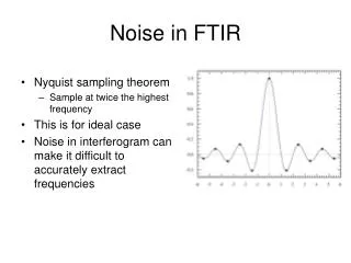
Problems with the application of IR Spectroscopy in-situ to the study of the electrode/electrolyte interface • All common solvents, and especially water absorb IR radiation very strongly. Water, e1640 = 20 mol-1 dm3 cm-1; to keep water absorption in this region down to 0.6, optical pathlength must be 5 mm, and preferably • c. 2 mm. • 2. High sensitivity and stability are required to be able to ‘pick out’ the very weak absorptions of the near electrode species, (mM – mM, and/or monolayer), from the intense background absorptions and noise.
These two problems are addressed thus: • In external reflectance spectroscopy by trapping a thin layer ( a few microns) of solution between the reflective WE and the cell window. This minimises the solvent absorption which is then anulled using differential data collection methodology. • Early in-situ IR systems used lock-in detection techniques which suffer from a number of problems including: complicated hardware and data collection, long measurement times, complicated data collection protocols. The advent of Fourier Transform InfraRed (FTIR) spectrometers rendered such techniques obselete.
The thin-layer configuration: External reflectance in-situ FTIRS A area above spectrometer, S spectrometer sample compartment. (a) IR beam in, (b) UV laser beam, (c) cooling/heating water in, (d) IR-transparent prism, (e) glass cell body, (f) water jacket, (g) Teflon cap and cell body, (h) thermo-couple leads, (i) contact wire, (j) electrolyte, (k) reflective working electrode.
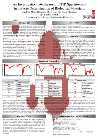
Data manipulation The reference spectrum, (R0, 8 cm-1 resolution, 16 or 100 co-added and averaged scans, 3s or 16s, respectively, per scanset), was collected at 1100 mV. The potential of the electrode was stepped up from -200mV and a series of spectra, Rn, collected as as a function of potential, or the potential was stepped and held, and spectra, Rn, collected as a function of time.
The spectra are presented as: (Rn/R0) vs /cm-1 Peaks pointing up, to +(Rn/R0), arise from the gain of absorbing species in Rn with respect to R0, and peaks pointing down, to -(Rn/R0), to the loss of absorbing species.
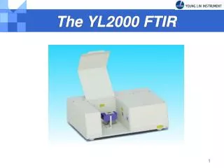
(1) The in-situ electrochemical FTIR cell; (2) BioRad FTS 6000 Spectrometer; [(3) 325nm Laser]; (4) Heated block controller; (5) Control PC; (6) Heating/ cooling unit; (7) Cooling/heating tubes to cell.


![Fourier transform infrared spectroscopy[FTIR]](https://cdn1.slideserve.com/2743434/fourier-transform-infrared-spectroscopy-ftir-dt.jpg)