Download

1 / 29
290 likes | 437 Vues
Safety and Transient Analysis for EFIT (ENEA 384MWth 3-Zone core). P. Liu, X. Chen, A. Rineiski, C. Matzerath Boccaccini, F. Gabrielli, W. Maschek (FZK) Forschungszentrum Karlsruhe, IKET Postfach 3640, D-76021 Karlsruhe Ping.liu@iket.fzk.de. IP EUROTRANS DM1.

E N D
Safety andTransient Analysis for EFIT (ENEA 384MWth 3-Zone core) P. Liu, X. Chen, A. Rineiski, C. Matzerath Boccaccini, F. Gabrielli, W. Maschek (FZK) Forschungszentrum Karlsruhe, IKET Postfach 3640, D-76021 Karlsruhe Ping.liu@iket.fzk.de IP EUROTRANS DM1 IP EUROTRANS DM1 WP1.5 Mtg. Madrid, Nov.13-14, 2007
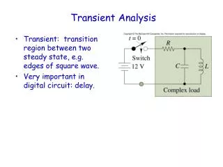
All calculations are performedtaking into account radial heat transfer between subassemblies Contents Analysis of the 3-Zone ENEA 384MWth core • Steady state analysis of the 3-zone core • Power,Temperatures, Void worth, Doppler etc. • Unprotected Loss of Flow (ULOF) • Unprotected Blockage Accident (UBA) Flow area reduced to 2.5% • UTOP (1000pcm jump in a 0.1s period in reactivity at HFP) • Beam Trip (5s beam trip case)
ENEA 384MWth 3Zone Core Design From Carlo Artioli, DM1-CC meeting-Orsay, Sept.26,2007
42 66 72 Coolant outlet to the heat exchanger Coolant inlet Core View and SIMMER-III Geometrical Model ENEA 3-Zone core SIMMER-III Geometrical Model of the EFIT Core
Steady-state Analysis – Continued SIMMER-III Calculated Peak Fuel Temperature: 1352.1 ℃; Peak Clad Temperature: 521.1 ℃ Limit temperatures: Fuel 1380 ℃, Clad 550 ℃; (From ENEA Files)
ENEA Steady-state analysis – Continued SIMMER-III In the inner core, SIMMER-III void worth in good agreement with ENEA; In outer core ring ~ 20% difference
ULOF Analysis • Assumptions: • Core - SG height difference 3.7 m; • Fast ULOF with 5 s pump halving time; • No structural thermal expansion taken into account (need for data); • The coolant inlet temperature kept constant at 400 ℃.
ULOF Analysis During ULOF, Power finally stabilized at about 1% higher than operational power. Reactivity finally stabilized at about 40-45 pcm higher than operation condition.
During ULOF, The coolant velocity decreases as shown in the left side figures. In turn, the coolant mass flow rate decreases, which finally stabilizes at around 40% due to the natural convection flow. Because of the remaining coolant flow rate, the coolant maximum temperature (TLK3) finally stabilizes at about 640℃ (913K).
ULOF Analysis –Continued • Final Pb flow rate stabilized at about 40%; • Maximum Pb temperature (at outer fuel ring) stabilized at about 640 ℃ (913K); • Maximum fuel temperature (at inner fuel ring) stabilized at about 1510 ℃ (1783K) (DBC-I limit 1750K,1477℃); • Maximum clad temperature (at inner fuel ring) stabilized at about 672 ℃ (945K).
UBA Analysis • Assumptions: • First fuel ring blocked and its flow area reduced to 2.5%; • Fuel pellets break up into particles after clad melting or clad failure; • In SIMMER-III, the fuel solidus temperature is defined as 2130K (MgO matrix evaporation limit), and the fuel liquidus temperature is defined as 2450K (melting of TRU); • UBA consequences depend on large parameter field (clad failure conditions, fuel failure conditions, above core structure behavior, hexcan failure conditions etc.).
Power and reactivity transients during UBA UBA Analysis
UBA Analysis-Continued • Pin failure after the clad looses its mechanical strength; • Gas blow-down and local voiding • Rewetting • Local fuel pellet ‘melting’; • Local Pb boiling; • Fuel sweep-out, reactivity and power reduction (25 %); • Beam shut-down necessary;
UTOP Analysis • Assumptions: • During 0.1s period, 1000pcm increase in reactivity(according to WP1.5 ad hoc definition)
UTOP analysis Increase of 1000 pcm in reactivity during 0.1s period: Power finally stabilizes at about 40 % higher than operational power. Reactivity finally stabilizes at about 1040 pcm higher than operational condition.
Maximum fuel temp. stabilizes at around 1750 ℃ (2023K) • Maximum fuel temp. above DBC-IV limit (1680 ℃). below DEC limit (1860 ℃) • Maximum clad temp. stabilizes at around 572℃ (845K); • Maximum coolant temp. stabilizes ataround 549 ℃ (822K).
Beam Trip Analysis • Assumptions: • External beam amplitude being zero for 5 seconds (according to WP1.5 ad hoc definition) .
Beam Trip Analysis With 5 seconds’ beam-off: Power decreases immediately and sharply; Reactivity nearly unchanged (small neutron flux shape and the coolant temperature reactivity effect).
Beam Trip Analysis-Continued • Fuel temp. at core mid-plane; • Coolant and clad temp. at core outlet • Maximum fuel temp. decreases about 720 ℃; • Maximum clad temperature decreases about 54℃; • Maximum coolant temperature decreases about 35 ℃.
Beam Trip Analysis-Continued • Temperature development at core mid-plane of first fuel ring.
Summary • Steady State Analysis • SIMMER simulated results are in agreement with the design data; • The EFIT core has a void worth larger than the sub-criticality; • The Doppler effect in EFIT core is about zero; • ULOF Analysis • Conservative assumptions • The power and reactivity increase is small; • The clad and coolant temp. are below their safety limits; • The fuel peak temperature is about 1510 ℃(1783K), which is between 1480 ℃ (DBC-I limit,1750K) and 1580 ℃ (DBC-II limit,1850K);
Summary - Continued • UBA Analysis • The power and reactivity increase is small; (Power increase less 5%) • Pin failure happens when the clad looses its mechanical strength; local Pb voiding possible, fuel stack disintegration; • No serious damage happens to neighbor fuel rings due to the inherent fuel sweep-out mechanism; • UBA, a transient with the potential of local core damage and damage propagation; • Outcome of UBA scenario dependent on many parameters; • UBA outcome connected with uncertainty band; • Special efforts needed and under way for improved understanding and simulation.
Summary - Continued • UTOP Analysis • The power increases 40% due to 1000pcm jump of the reactivity; • No pin failure happens; • The maximum fuel temp. is around 1750 ℃ (2023K) (higher than DBC-IV limit 1680 ℃,1950K), clad 572 ℃ (845K), coolant 549 ℃ (822K); • Beam Trip Analysis • With a 5 seconds beam-off, the maximum fuel temperature decreases about 720 ℃, the maximum clad temperature transiently decreases 54 ℃, the maximum coolant temperature decreases 35 ℃. • Fuel behaviour after multiple beam trips