Transient Analysis in R-L and R-C Circuits and Energy Storage | Circuit Theory Example Problems
Learn about transient analysis in R-L and R-C circuits, voltage and current growth/decay, time constants, and energy storage calculations with practical examples. Solve for currents, voltages, energies, and waveform plotting.


Transient Analysis in R-L and R-C Circuits and Energy Storage | Circuit Theory Example Problems
E N D
Presentation Transcript
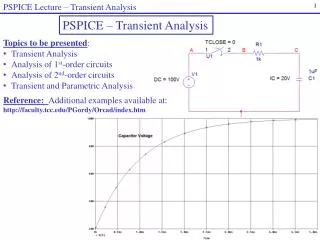
Transient Analysis Transient Analysis
i vR vL The Growth of current in R-L Circuit When switch S just switches to a : t=0 , i=0 , VL =0 Then current start flowing with the rate of di/dt thus a voltage develop in inductor given by
i vR vL Using Voltage Kirchoff’s law Divided by R Where I = V/R = steady current = L/R = time constant
Rearrange the equation Integrate both sides we have (*) Then the solution is Apply the initial state t=0 and i=0 Substitute in (*) , we have Or Voltage Substitute t = L/R
vL, i V vL, V/R i t 0
vR vL i Decay analysis for R-L circuit When switch S is switched to b iL will begin to decay in a reverse direction with the rate of di/dt thus a voltage develop in inductor given by
Using Voltage Kirchoff’s law Or Rearrange where = L/R Integrate The solution Apply initial condition t=0 , i=I Or we have
vL, i V/R i + 0 t - vL V Voltage Substitude = L/R and IR = V; we have vL = - V e-t/
Example 1 • For network as in figure • Determine the mathematical expressions for the variation of the current in the inductor following the closure of the switch at t=0 on to position 1 • When the switch is closed on to position 2 at t=100ms, determine the new expression for the inductor current and also for the voltage across R; • Plot the current waveforms for t=0 to t=200ms.
(a) For the switch in position 1, the time constant is Therefore (b) For the switch in position 2, the time constant is Therefore The voltage drop
At time t=0 till t=40ms ifollows the equation At time t=40ms till t=100ms i is saturated which is equaled to 1 At time t>100ms i follows the equation
Example 2 For the network in example 1, the switch is closed on to position 1 as before but it is closed on to position 2 when t=10ms. Determine the current expressions and hence plot the current waveforms When switch is switched on to position 1 , i follows At t=10ms the magnitude of i is When switch is switched on to position 2 , i
Example 3 For network in the Figure , the switch is closed on to position 1 when t=0 and then moved to position 2 when t=1.5ms. Determine the current in the inductor when t=2.5ms.
First we simplify the supply of the circuit using Norton Theorem The simplified circuit is
Switch at position 1 Current Maximum magnitude At time t=1.5ms Switch at position 2 t2=2.5ms- t1=2.5ms-1.5ms=1ms
Energy stored To neutralize the induced e.m.f which represents the power absorbed by magnetic field a voltage source is needed. The energy produced by the voltage and current developed is stored in the form of magnetic field. This is given by and Average energy absorbed Total energy absorbed
i vR vC The Growth of current in R-C Circuit When switch S just switches to a : t=0 , q=0 , VC =0 Then voltage start develops across the capacitor with the rate of dVC/dt thus a current flowing in the circuit is given by
i vR vC Using Voltage Kirchoff’s law V = vR + vC Or V – vC = vR = iR Substitute i we have Or Where t =RC
Rearrange we have Integrate Then we have At t=0 we have vC=0 thus A=ln V Substitute A we have Or
vC, i vC V V R i t Voltage development and current decay in serial RC circuit Substitute VC in the current formulation
i vR vC Decay analysis for R-C circuit When the switch is connected to b, vC = V. The accumulated charges in C now start to discharge via R. The initial current iI is given by: In the process of discharging, voltage across C, vC is decaying. When charges are full discharged, vC = 0 and the final current iF = 0.
Using voltage‘s Kirchoff law vC = -vR Therefore But Substitute we have And substitute Rearrange RC = Then we have
Integrate We get A = ln V If t=0 ; vC=V , then we have Substitute A we have We get or
vC, i V vC 0 t i -V/R Decaying of Voltage and currrent in RC circuit For current we have
Example 4 A capacitor is made of two pieces of aluminium foil separated by a piece of paper of 0.2mm thick and having a relative permittivity of r = 5. Determine the area of aluminium required to produce a capacitance of 1200 pF? Assume that the permittivity of the free space is o ,8.854 x 10-12 F/m. C = 1200 pF = 1200 x 10-12 F d = 0.2 mm = 2 x 10⁻⁴ m r = 5; dan o = 8.854 x 10⁻¹² F/m A = ?
Example 5 • Two capacitors, C1 = 1200 pF and C2 = 2200 pF are connected in parallel. The combination is connected to an a.c voltage source VS = 155 V having a series resistor RS. After the voltage across the capacitor reach a steady state, the connection of capacitor to the battery is disconnected and discharged via a resistor RP. • Draw the circuit. • Calculate Rs so that the energy stored in capacitor reaches 25 mJ in 250ms during capacitor charging • Calculate Rp , after 1msdischarging, the voltage drop is 20% from its steady state. • Calculate the energy stored in capacitor after 1.5ms discharging.
RS VS 155 V RP C2 2200 pF C1 1200 pF (1)
(2) Total capacitance Given Voltage across cap. or During charging rewrite or then
(3) During discharging Given that vc drop 20% from its steady voltage , vC= 0.8VS or
(4) After 1.5ms discharge