Transient Overvoltages
Transient Overvoltages. Sources of transient overvoltages. Capacitor switching switching a single capacitor switching back-to-back capacitors transient “magnification” Other methods to improve power factor - Synchronous condenser - power electronics device (VSC/STATCOM).

Transient Overvoltages
E N D
Presentation Transcript
Sources of transient overvoltages • Capacitor switching • switching a single capacitor • switching back-to-back capacitors • transient “magnification” • Other methods to improve power factor - Synchronous condenser - power electronics device (VSC/STATCOM)
Sources of transient overvoltages • Other switching transients • line energizing • faults • Lightning • Ferroresonance • May be sustained, not transient
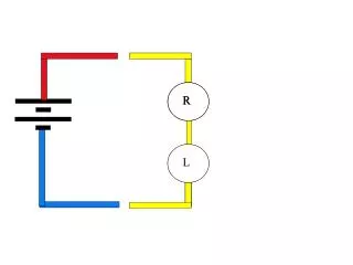
Capacitor switching Substation Feeder impedance V HV system Thevenin equivalent A Switched capacitor Current and voltage measurements One-line diagram showing location of switched capacitor and measurement location on distribution feeder circuit
Capacitor switching ia Feeder Z va Switched capacitor HV system Thevenin equivalent Sinusoidal forced response (AC steady state) plus natural (transient) response
Magnification of capacitor switching transient by customer capacitor • customer’s capacitor bank on LV side of service transformer will see the voltage transient produced by utility capacitor switching (on MV or HV system). • if the resonant frequency is close to the frequency produced by the utility capacitor, the customer’s capacitor bank will appear to magnify the oscillation locally.
Substation Service transf Load HV system Thevenin equivalent L1 L2 capacitor One-line diagram showing location of switched capacitor and customer with LV capacitor which may magnify switching transient
This may require customer to install high-energy MOV surge arresters • Customer may install a small inductor (called a reactor) in series with the capacitor bank • added advantage of improving harmonic performance (next chapter) • if a few drives are all that are affected, then the inductor can be added there
Back to back capacitor switching Substation Service transf HV Thevenin equivalent capacitors Charging one capacitor from the other through a very small inductance. Rise time on inrush current waveform is very high, with high-frequency oscillation.
Lightning • Lightning surge may enter from • strike to HV or MV (primary) line supplying customer • nearby strike to ground • strike to LV (secondary) line on or near customer premise • strike to customer building or other structure
Transformer model at high frequencies Capacitively coupled impulse due to Interwinding capacitance of transformers A a … G G N N vAG(t) vaG(t) t t
Transformer model at high frequencies A a vaG(t) N t G Longer pulses may be conducted around transformer
Ferroresonance • Nonlinear resonance between unloaded transformer magnetizing branch and a series capacitor • May occur when distribution transformers fed from cables are switched one phase at a time • Especially a problem on ungrounded wye-delta transformers • May occur any time an unloaded iron-core coil is in series with a capacitor
Long-duration overvoltage caused by ferroresonance of transformer
Ferroresonant circuit I VL = jwL I = E - VC VC VL E VC = [1/(jwC)] I =-j [1/(wC)] I XC = 1/(wC) XL jI VL = XL jI = E + XC jI VL E + XC jI jI
Ferroresonant circuit VL = XL jI = E + XC jI slope = XC slope=XL VL jI
Ferroresonant circuits A B C A B C
Possible effects of ferroresonance • Overvoltage • Audible noise • Overheating • Sustained overvoltage => arrester failure • Flicker due to erratic voltage • Subharmonic voltages (e.g., at 1/3 or 1/2 of normal frequency) • Chaotic response