Download
1 / 45
541 likes | 1.38k Vues
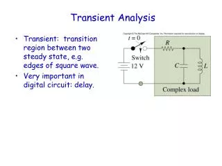
DC TRANSIENT ANALYSIS. CHAPTER 5. Objectives. Investigate the behavior of currents and voltages when energy is either released or acquired by inductors and capacitors when there is an abrupt change in dc current or voltage source.

E N D
DC TRANSIENT ANALYSIS CHAPTER 5
Objectives • Investigate the behavior of currents and voltages when energy is either released or acquired by inductors and capacitors when there is an abrupt change in dc current or voltage source. • To do an analysis of natural response and step response of RL and RC circuit.
Lecture’s contents • 5-1 NATURAL RESPONSE OF RL CIRCUIT • 5-2 NATURAL RESPONSE OF RC CIRCUIT • 5-3 STEP RESPONSE OF RL CIRCUIT • 5-4 STEP RESPONSE OF RC CIRCUIT
Vs R R i i – + – + vs L C An RC circuit An RL circuit First – Order Circuit • A circuit that contains only sources, resistor and inductor is called and RL circuit. • A circuit that contains only sources, resistor and capacitor is called an RC circuit. • RL and RC circuits are called first – order circuits because their voltages and currents are describe by first order differential equations.
RTh VTh – + IN RN L C Review (conceptual) • Any first – order circuit can be reduced to a Thévenin (or Norton) equivalent connected to either a single equivalent inductor or capacitor. • In steady state, an inductor behave like a short circuit. • In steady state, a capacitor behaves like an open circuit.
The natural response of an RL and RC circuit is its behavior (i.e., current and voltage ) when stored energy in the inductor or capacitor is released to the resistive part of the network (containing no independent sources) • The steps response of an RL and RC circuits is its behavior when a voltage or current source step is applied to the circuit, or immediately after a switch state is changed.
t = 0 i + V – Is Ro L R 5-1 Natural Response of an RL circuit • Consider the following circuit, for which the switch is closed for t<0, and then opened at t = 0: • The dc voltage V, has been supplying the RL circuit with constant current for a long time
i + v – Io Ro L R Solving the circuit • For t ≤ 0, i(t) = Io • For t ≥ 0, the circuit reduce to • At t = 0, the inductor has initial current Io, hence i(0) = Io • The initial energy stored in the inductor is,
(1) (2) (3) (5) (4) Cont. • Applying KVL to the circuit: • From equation (4), let say;
(6) (7) Cont. • Integrate both sides of equation (5); • Therefore, • hence, the current is
Cont. • From the Ohm’s law, the voltage across the resistor R is: • And the power dissipated in the resistor is: • Energy absorb by the resistor is:
Time Constant, τ for RL circuit • Time constant, τ determines the rate at which the current or voltage approaches zero. • The time constant of a circuit is the time required for the response to decay to a factor of 1/e or 36.8% of its initial current • Natural response of the RL circuit is an exponential decay of the initial current. The current response is shown in Fig. 5-1 • Time constant for RL circuit is • And the unit is in seconds. Figure 5-1
The expressions for current, voltage, power and energy using time constant concept:
∞ -∞ Switching time • For all transient cases, the following instants of switching times are considered. • t = 0- , this is the time of switching between -∞ to 0 or time before. • t = 0+ , this is the time of switching at the instant just after time t = 0s (taken as initial value) • t = ∞ , this is the time of switching between t = 0+ to ∞ (taken as final value for step response) • The illustration of the different instance of switching times is:
2Ω i0 t = 0 + V – 0.1Ω 10Ω 2H 20A 40Ω iL Example 1 • For the circuit below, find the expression of io(t) and Vo(t). The switch was closed for a long time, and at t = 0, the switch was opened.
2Ω 2Ω io(0+) + vo(0+) – 20A 10Ω 2H 0.1Ω 10Ω 40Ω 40Ω 20A iL(0+) iL(0-) Solution : • When t < 0, switch is closed and the inductor is short circuit. • When t > 0, the switch is open and the circuit become; Therefore; iL(0-) = 20A Hence; iL(0+) = iL(0-) = 20A Current through the inductor remains the same (continuous)
RT = (2+10//40) = 10Ω So, time constant, sec By using current division, the current in the 40Ω resistor is: Using ohm’s Law, the Vo is, Hence:
+ 2Ω 4Ω t = 0 i(t) 12Ω 40V 16Ω 2H Example 2 The switch in the circuit below has been closed for a long time. At t = 0, the switch is opened. Calculate i(t) for t > 0.
2Ω 4Ω i1 12Ω i(0-) 40V + Solution : • When t < 0, the switch is closed and the inductor is short circuit to dc. The 16Ω resistor is short circuit too. calculate i1; using current division, calculate i(0-) Since the current through an inductor cannot change instantaneously Hence; i(0) = i (0-) = 6A
4Ω i(t) 12Ω 16Ω 2H hence; • When t > 0, the switch is open and the voltage source is disconnect. i(0+) = i(0) = i (0-) = 6A Because current through the inductor is continuously RT = Req = (12 + 4)// 16 = 8Ω Time constant, Thus,
t = 0 Ro + v – + Vo R C 5-2 Natural Response of an RC Circuit • The natural response of RC circuit occurs when its dc source is suddenly disconnected. The energy already stored in the capacitor, C is released to the resistors, R. • Consider the following circuit, for which the switch is closed for t < 0, and then opened at t = 0:
i + v – Ro + Vo C R Solving the circuit • For t ≤ 0, v(t) = Vo • For t > 0, the circuit reduces to • At t = 0, the initial voltage v(0) = Vo • The initial value of the energy stored is
Cont. (1) • Applying KCL to the RC circuit: (2) (3) (4) (5)
Cont. (6) • From equation (5), let say: • Integrate both sides of equation (6): • Therefore: (7) (8)
Cont. • Hence, • The voltage is: • Using Ohm’s law, the current is: • The power dissipated in the resistor is: • The energy absorb by the resistor is:
Time Constant, τ for RC circuit • The time constant for the RC circuit equal the product of the resistance and capacitance, • Time constant, sec • The natural response of RC circuit illustrated graphically in Fig 5.2 Figure 5.2
The expressions for voltage, current, power and energy using time constant concept:
5kΩ 18kΩ a b t = 0 + Vo – + 90V 10kΩ 12kΩ 60kΩ 0.1μF Example 3 The switch has been in position a for a long time. At time t = 0, the switch moves to b. Find the expressions for the vc(t), ic(t) and vo(t).
At t < 0, the switch was at a. the capacitor behaves like an open circuit as it is being supplied by a constant source. At t > 0, the instant when the switch is at b. 5kΩ + Vc(0-) – 90V 10kΩ + 18kΩ + Vo – + Vc(0+) – 60kΩ 12kΩ 0.1μF Solution the voltage across capacitor remains the same at this particular instant vc(0+) = vc(0-) = 60V
RT = (18 kΩ + 12 kΩ) // 60 kΩ = 20 kΩ time constant, τ = RTC = 20kΩ x 0.1 μF = 2ms Vc(t) = 60e-500t V Using voltage divider rule, Hence, Vo(t) = 24e-500t V
t = 0 1Ω 3Ω + v – 20V 9Ω 20mF + Example 4 The switch in the circuit below has been closed for a long time, and it is opened at t = 0. Find v(t) for t ≥0. Calculate the initial energy stored in the capacitor.
3Ω 1Ω + vc(0-) – 20V 9Ω 1Ω + + vc(0+) – 9Ω 20mF Solution For t<0, switch is closed and capacitor is open circuit. For t>0, the switch is open and the RC circuit is
Because; Req = 1+9 = 10Ω So ; Time constant, τ = ReqC = 0.2s Because; vc(0) = vc(0+) = vc(0-) = 15 V v(t) = 15e-5t V Voltage across the capacitor; Initial energy stored in the capacitor is; wc(0) = 0.5Cvc2 =2.25J
+ v(t) – L t = 0 R Vs + i 5-3 Step Response of RL Circuit • The step response is the response of the circuit due to a sudden application of a dc voltage or current source. • Consider the RL circuit below and the switch is closed at time t = 0. • After switch is closed, using KVL (1)
Cont. (2) • Rearrange the equation; (3) (4) (5) • Therefore: (6)
Cont. • Hence, the current is; • Or may be written as; Where i(0) and i(∞) are the initial and final values of i, respectively. • The voltage across the inductor is; • Or;
t = 0 3Ω 2Ω 10V 1/4H + Example 5 The switch is closed for a long time at t = 0, the switch opens. Find the expressions for iL(t) and vL(t). i
2Ω 10V iL(0-) + + 3Ω 2Ω 10V 1/4H Solution When t < 0, the 3Ω resistor is short – circuit, and the inductor acts like short circuit. When t< 0, the switch is open and the both resister are in series. So; i(0) = i(0+) = i(0-) = 5A iL(0+) Because inductor current cannot change instantaneously
3Ω 2Ω 10V iL(∞) + Time constant; When t = ∞, the inductor acts as short circuit again. Thus: iL(t) = i(∞) +[i(0) – i(∞)]e-t/τ = 2 + 3e-20t A = -15e-20t V And the voltage is:
+ vc(t) – t = 0 Is R C i 5-4 Step Response of RC Circuit • Consider the RC circuit below. The switch is closed at time t = 0 • From the circuit; • Division of Equation (1) by C gives; (1) (2)
Cont. • Same mathematical techniques with RL, the voltage is: • Or can be written as: • And the current is: • Or can be written as: v(t) = v(∞) + [v(0) – v(∞)]e-t/τ
3kΩ 4kΩ a b t = 0 + Vc – 24V 5kΩ 30V + + 0.5mF Example 6 The switch has been in position a for a long time. At t = 0, the switch moves to b. Find Vc(t) for t > 0 and calculate its value at t=1s and t=4s
3kΩ 4kΩ + Vc (0-) – 24V 5kΩ 30V 0.5mF + + Solution When t<0, the switch is at position A. The capacitor acts like an open circuit. Using voltage division: Since voltage across the capacitor remains same. When t <0, the switch is at position B. And the time constant is:
+ 4kΩ + Vc(∞) – 30V At t = ∞, the capacitor again behaves like an open circuit. Hence; Since, v(t) = v(∞) + [v(0) – v(∞)]e-t/τ So; vc(t) = 30-15e-0.5t V And; At , t = 1s, Vc(t) = 20.9V At , t = 4s, Vc(t) = 28 V