Download
1 / 16
160 likes | 332 Vues
A demonstrator for the CBM Time of Flight wall electronic readout chain. People: GSI: M. Ciobanu, H. Deppe, H. Flemming, J. Frühauf, D. Gonzalez-Diaz, M. Kis, K. Koch, S. Linev, W. F.J. Müller KIP: N. Abel, U. Kebschull , S. Manz

E N D
A demonstrator for the CBM Time of Flight wall electronic readout chain People: GSI:M. Ciobanu, H. Deppe, H. Flemming, J. Frühauf, D. Gonzalez-Diaz, M. Kis, K. Koch, S. Linev, W. F.J. Müller KIP: N. Abel, U. Kebschull , S. Manz PI: N. Herrmann, P.-A. Loizeau, I. Deppner, K. Wisniewski Pierre-Alain Loizeau PI – Uni Heidelberg DPG Bonn – March 2010 -Session: HK 48
1. Main requirements for the electronics 2. Readout chain demonstrator design 3. Current components of the demonstrator 4. Clock synchronization 5. First observations on the full chain Conclusion & Outlook P.-A. Loizeau –DPG Bonn –March 2010 –Session HK 48
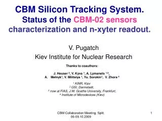
1. Main requirements for the electronics Rate per electronic channel, Au+Au at 25 AGev, mbias, 10 MHz interaction rate, field scaling = 0.720 (from a simulation by A. Kiseleva) • ~75000 channels • Global electronic time resolution < 30ps (TDC < 25ps) • Self triggered system(Timestamp & Epoch markers) • Compatible readout, synchronization and time domain with other detectors • Low power consumption: < 60 mW/ch (~30mW/ch for both Analog and TDC) Information about the conceptual design: see I. Deppner talk in Session HK58 P.-A. Loizeau –DPG Bonn –March 2010 –Session HK 48
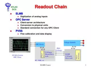
PC Online/ OfflineAnalysis GO4 FAIRROOT CLOSY2 + Distribution Sync TDC Sync TDC CLK156 CLK250 CLK156 ABB Opt A R2F (AD1) CLK156 CLK250 ROC Sync TDC A Opt Opt B CBMM-RPCDemo 1 PCIe B C Eth A DABC D PADI PADI PADI PADI PADI PADI GET4 GET4 GET4 GET4 GET4 GET4 SYNC-S E B AUX F Startcounter G Hybrid DAQSystem: triggered + time-stamped 2. Readout chain demonstrator design Data readout, Epoch synchronization check, first data aggregation Other systems: nXYTER, … 156/250 MHzclock & SYNC_TDCdistribution A RPCTestBench someauxdets SYNCmessagesender FOPI RPCTest Environment MBS System P.-A. Loizeau –DPG Bonn –March 2010 –Session HK 48
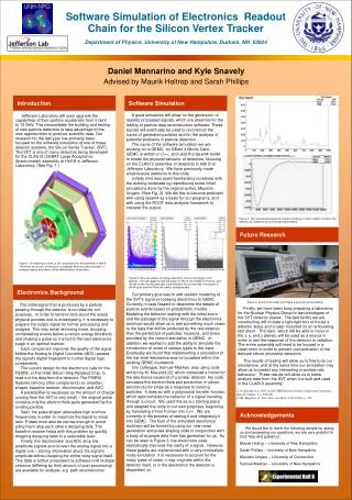
3. Components: Front end Analog part: Fast Pre-Amplifier & Discriminator • PADI project by M. Ciobanu at GSI-DetLab • Performances: resolution<15ps rms Digital part: Free running High Resolution TDC • GET4 project at GSI by H. Deppe & H. Flemming from GSI-EE: See first talk of this session • Performances: ~25ps rms resolution, data readout >150 kHz/ch possible Clock System: Generate 2 low jitter phase coupled clocks and a synchronization signal for GET4 and ROC • CLOSY2 (Cbm-cLOck-SYnthesizer) developed at GSI by K. Koch from GSI –EE P.-A. Loizeau –DPG Bonn –March 2010 –Session HK 48
3. Components: readout & aggregation ROC: FEB readout, first data processing, synchronization, FEB control • SYSCORE v2 based solution • Firmware developed at KIP by S. Manz: see previous talk Software environment: • DAQ: DABC = Data Acquisition Backbone Core (HK49.1) • Data analysis: GO4 = GSI Object Oriented On-line-Offline (HK30.2) Developed by J.Adamczewski-Musch, S.Linev, M.Al-Turany, D.Bertini & H.G.Essel (GSI - EE) P.-A. Loizeau –DPG Bonn –March 2010 –Session HK 48
4. Clocks Synchronization Why so important? • 2 free running systems with different clocks in CBM =>Event building! • 75000 channels ~19000 TDC chips with current design, with measure of each hit against the received clock! In the CLOSY2 system: • Sync signal generated every 5th coincidence • Correspond to 25 GET4 Epoch • Correspond to 40 NXYTER timestamp cycle P.-A. Loizeau –DPG Bonn –March 2010 –Session HK 48
5. First observations on the full chain • Assembled for the first time middle of February • Using first version of the ROC firmware and an online analysis tool • In a first time focus on hardware checks: -2 FEET-TDC & 3 FEET-PADI tested -Presence of all voltages & error messages -Clock system: Synchronization of the epochs between chips and between the 2 clock signals=> every 25 epochs Results: • The readout of the chain using current versions of the electronic components and of the FAIR software environment is working • 1 FEET-TDC board was operated successfully with all voltages at nominal value and no synchronization error messages P.-A. Loizeau –DPG Bonn –March 2010 –Session HK 48
Conclusion • The full readout chain for the demonstrator of the CBM ToF wall is a project involving 4 different groups, with strong requirement on the time resolution • Each of its components showed performance meeting the requirements during individual tests • This readout chain is now assembled for the first time since a few weeks and tests just started Goals • Building & testing a full demonstrator including a differential RPC, with 64 channels (32 strips), until end of 2010 • Demonstration of the readout chain performance with different kinds of Multi-Gap Resistive Plate Chambers P.-A. Loizeau –DPG Bonn –March 2010 –Session HK 48
Thank you for your attention P.-A. Loizeau –DPG Bonn –March 2010 –Session HK 48
FEET-PADI VME readout and evaluation system (Pulser) Closy2 CAEN v1290A Rising edge FEET-PADI Splitter VME & MBS Readout System Splitter CAEN v1290A Falling edge PC Online/ OfflineAnalysis GO4 P.-A. Loizeau –DPG Bonn –March 2010 –Session HK 48
HDM-RPC PMT PADI2 VME readout and evaluation system with TACQUILA system (BEAM) PC PADI TACQUILA + ToT board PADI PAW PADI TACQUILA + ToT board PADI START Card TACQUILA RPCTestBench someauxdets FOPI RPCTest Environment MBS System P.-A. Loizeau –DPG Bonn –March 2010 –Session HK 48
CLOSY2 Sync TDC Sync TDC CLK156 CLK250 CLK156 AD-1 (R2F) CLK156 CLK250 ROC Sync TDC A Opt B C Eth A D FEET - PADI FEET - TDC SYNC-S E B AUX F G System for the first full chain tests PC Online/ OfflineAnalysis GO4 156/250 MHzclock & SYNC_TDCdistribution Pulser A RocUtils P.-A. Loizeau –DPG Bonn –March 2010 –Session HK 48
Minimal Numbers of boards for each electronic layer per SM: Total number of channels: ~75500! Total ROCs: ~710! P.-A. Loizeau –DPG Bonn –March 2010 –Session HK 48