Download

1 / 26
260 likes | 421 Vues
A 20 ps TDC readout module for the Alice Time of Flight system: design and test results. P. Antonioli INFN- Bologna On behalf of the ALICE-TOF Group. Outline. A brief overview of the ALICE-TOF detector and its readout system

E N D
A 20 ps TDC readout module for the Alice Time of Flight system: design and test results P. Antonioli INFN- Bologna On behalf of the ALICE-TOF Group 2 October 2003 P. Antonioli (INFN/Bologna)
Outline • A brief overview of the ALICE-TOF detector and its readout system • The ALICE/TOF TDC Readout Module (based on HPTDC from CERN) conceptual design • Card prototypes results: • Integral Non-Linearity effects • Resolution study • Test on magnetic field • Test with real data • Crosstalk issues • Conclusions and outlook 2 October 2003 P. Antonioli (INFN/Bologna)
The ALICE TOF detector Detector based on MultiGap Resistive Plate Chambers, which can reach excellent intrinsic time resolution ( 50 ps) MRPC detector providing PID information 160,000 ch < 100 ps resolution required 2 October 2003 P. Antonioli (INFN/Bologna)
Readout scheme ONE TOF SECTOR Modules Cable route TRMs DRM + LTM TOF readout crate 18 TOF sectors for a total of 160,000 ch. FEE provides pre-amplification, discrimination and shaping realized with a custom ASIC. Output: LVDS 2 custom VME64x crates positioned at the end of each sector. Each crate hosting 10 TDC card (240 ch, with 30 HPTDC on board) + readout and trigger modules 2 October 2003 P. Antonioli (INFN/Bologna)
TRM uses HPTDC TRM card is based on HPTDC chip developed at CERN by Microelectronic group. HPTDC is capable in its Very High Resolution Mode of 24.4 ps bin size. HPTDC has LVDS inputs, internal buffers, multi-hit, multi-event and trigger matching capabilities and it is also able to measure pulse width (sensitive to leading and trailing edges). In VHRM: 8 ch/chip. Three versions of the chip released before its finalproduction (2003/4). 27 mm 2 October 2003 P. Antonioli (INFN/Bologna)
HPTDC architecture HPTDC is fed by a 40 MHz clock giving us a basic 25 ns period (coarse count). A PLL (Phase Locked Loop) deviceinside the chip does clock multiplication by a factor 8 (3 bits) to 320 MHz (3.125 ns period) . ADLL (Delay Locked Loop)done by 32 cells fed by the PLL clock acts a 5 bits hit register for each PLL clock (98 ps width LSB = 3.125 ns/32). 4R-C delay linesdivides each DLL bin in 4 parts (R-C interpolation) 2 October 2003 P. Antonioli (INFN/Bologna)
TRM conceptual design HPTDC HPTDC TRG ReadoutController 32 x 15 VMEInterface Output Fifo L1 32 TRG INPUTS (LVDS) INPUTS (LVDS) 32 32 x 15 VME bus 32 L2a EventManager DSP L2r L2a L2r SRAM 32 32 SRAM 32 2 October 2003 P. Antonioli (INFN/Bologna)
Notes on TRM architecture • The VME bus is a robust industrial standard. Even if currently not needed (conservative required bandwidth of the card is 16 MB/s) firmware upgrade to 2eVME possible. • The design is highly flexible: different readout schemes and data processing can be applied during the life cycle of the experiment, when needed. • For the DSP high level tools are available, making easier code maintenance and upgrades. 2 October 2003 P. Antonioli (INFN/Bologna)
Integration with Trigger HPTDC matching window (100ns) MRPCHits Interactiontime HPTDC trigger latency = L1 latency Hits moved to HPTDC readout FIFOs on L1 (matching) 6.7 ms L1 Readout Controller move hits from readout FIFO to TRM event buffer through Event Manager. DSP receives and processes data. On L2 accept, DSP transfers packed event to Output Fifo. On L2 reject DSP discards data. 94.7 ms L2 DSP provides: data packing, INL correction, and data monitor at first level trigger 2 October 2003 P. Antonioli (INFN/Bologna)
TRM development cards HPTDC HPTDC L2r L2a SRAM 32 32 SRAM ReadoutController TRG 32 VMEInterface x 15 Output Fifo L1 32 Separate HPTDC issues from readout and data processing TRG 32 32 x 15 32 L2r EventManager DSP L2r 32 2 October 2003 P. Antonioli (INFN/Bologna)
Integral non linearity HPTDC 1.3: INL still there but effect reduced. INL compensation through look-up tables needed HPTDC shows INL pattern in its high resolution modes • Main source of INL pattern is clock noise from the logic part through the power supply • same “pattern” of INL observed in different chip and channels • values of RMS (as estimated through INL) between 40-60 ps 2 October 2003 P. Antonioli (INFN/Bologna)
Time resolution Without INL compensation Without INL compensation After INL compensation After INL compensation Time resolution tested through delay lines. Resolution after apply INL compensation under control, more channels tested simultaneously. Can we do better? 2 October 2003 P. Antonioli (INFN/Bologna)
Refined INL correction Basic idea: we known INL compensation table with resolution better than +/- 1 HPTDC LSB. What happen if we apply a better approximation to INL (2 bits more 0.,0.25,0.5,0.75...)? 2 October 2003 P. Antonioli (INFN/Bologna)
Refined INL correction (2) 1 bin INL comp. table Adding two bits using pseudo-bins of 6.1 ps we can reach resolution near 15 ps... 0.25 bin INL comp. table 2 October 2003 P. Antonioli (INFN/Bologna)
Impact on overall resolution From board to boardWithin boardWith refined INL treatment s2 = s2MRPC + s2T0 + 2s2TDC + s2clock + s2clockTRM Reference values:MRPC 50 psT0 50 psTDC 25 psCLOCK 15 psCLTRM 10 ps Contribution of each component to the total (1.5%) (3.5%) (19%) (39%) Total: 81 ps (39%) 2 October 2003 P. Antonioli (INFN/Bologna)
R-C calibration Calibrating R-C lines we divide 98 ps bin to obtain 24.4 ps LSB Expected relative occurrency of each R-C line: 0.25 Substantial improvement with HPTDC 1.3 2 October 2003 P. Antonioli (INFN/Bologna)
TOT capability check TOF reminder: we use leading and trailing edges getting width to avoid amplitude measurement for time slewing correction. Check of minimal width detectable by the HPTDC (leading and trailing edges) 6 ns pulse width looks safe, however small variations between chips expected: FEA ASIC of ALICE/TOF expected to safely stretch pulses. 2 October 2003 P. Antonioli (INFN/Bologna)
Test in magnetic field Magnet to be setup for EXOTIC experiment at INFN Legnaro laboratories. HPTDC slave card tested up to 0.5 T last 5 May No functional problems observed; 0 errors detected INL pattern unchanged Space for an HPTDC slave card 2 October 2003 P. Antonioli (INFN/Bologna)
Test beam results We showed with lab test HPTDC can achieve 20 ps resolution. During tests beam, MRPC real data measured with HPTDC. Obtained time resolutions (and efficiencies) fully compatible with “standard” (measured with CAMAC LeCroy TDCs) ones. 2 October 2003 P. Antonioli (INFN/Bologna)
Test beam results (2) May 2003:ASIC+HPTDC 2 October 2003 P. Antonioli (INFN/Bologna)
Crosstalk measurements Ch. 0 START Signal Ch. 1-7 Noise signal HPTDC Ds Cross Talk check: Analyzing shifts of Tstart-Tstop varying Ds Tstart-Tstop Ch. 0-7 STOP Signal HPTDC 2 October 2003 P. Antonioli (INFN/Bologna)
Crosstalk measurements Test repeated over many channels. Larger measured crosstalk at level of 1 LSB 2 October 2003 P. Antonioli (INFN/Bologna)
Crosstalk measurements NO Due to charge sharing between pads, there is a distinct probability to have two hits when particle cross near pad boundaries. It is also normal to observe resolution worsening near the boundary (lower charge collected). Is there a measurable additional contribution from HPTDC? 2 October 2003 P. Antonioli (INFN/Bologna)
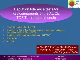
Radiation tolerance Irradiation next 24/25 November Devoted HPTDC test card for heavy ions irradiation @ SIRAD Currently only one measurement done by CMS at Louvain on HPTDC (1.1): extrapolating their measurement we can expect 1-2 SEU/day on the whole experiment. Low radiation levels expected at ALICE/TOF: 0.3 Gy/10 years and total neutron fluence of 2 109 /cm2/10 years At INFN Legnaro Lab. we will chacterize energy threshold for SEU in HPTDC registers using heavy ions. Additional measurement with protons possibly at Louvain next year. SIRAD facility at Legnaro for irradiation with heavy ions 2 October 2003 P. Antonioli (INFN/Bologna)
Towards final TRM layout • Key ingredients: • • FPGA: Altera ACEX with 100,000 gates• DSP: Analog Devices Sharc ADSP-21160N: • - 0.18 mm technology - large enough memory resources (4Mbits) • • Latch-up protection • • SEU “tolerant” • • Firmware upgrade through VME • To reduce board complexity and make easier maintenance: • • use 10 piggy-back cards hosting each 3 HPTDC + local voltage regulator (24 ch matches FEA nr. Of channels and connector) mounted on each side;• a central mother board for FPGA/DSP/memory etc. 2 October 2003 P. Antonioli (INFN/Bologna)
HPTDC tested and qualified for ALICE/TOF use(20 ps resolution) All “building bricks” of final TRM card tested, final TRM layout in advanced preparation TRM production due starting during 2004 Conclusions and outlook 2 October 2003 P. Antonioli (INFN/Bologna)