Download
1 / 9
90 likes | 250 Vues
Use of ALICE T0 Electronics for BPTX Readout. David Evans. The T0 detector in ALICE Requirements of the T0 detector and electronics Timetable / Progress of T0 system Suitability for BPTX What next ?. Purpose of the T0 Detector. T0 is a triggering detector for level 0 trigger

E N D
Use of ALICE T0 Electronicsfor BPTX Readout David Evans • The T0 detector in ALICE • Requirements of the T0 detector and electronics • Timetable / Progress of T0 system • Suitability for BPTX • What next ?
Purpose of the T0 Detector • T0 is a triggering detector for level 0 trigger • Gives rough on-line vertex • Beam-gas suppression • Gives rough on-line centrality measurement for trigger • Acts as pre-trigger for TRD
Position of T0 in ALICE T0L -5 < h < -4.5 T0R2.9 < h < 3.3 3.5 m 0.7 m
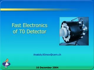
T0– the final configuration: • Two arrays of 12 PMTs with quartz radiators • T0 Right ( + 0.7 m) • T0 Left ( - 3.5 m) • Two shoe boxes of fast electronics inside the magnet (+5 m and –5 m) • Few creates of electronics outside the magnet • Laser calibration system also outside the magnet
Requirements of T0 • Precise timing (50 ps) • Fast read-out (used for L0 trigger) • Event spacing 25 ns (pp) L1 L2 T =L1 /c –L2 /c L1 L2 T = (L1+L)/c – (L2 - L)/c = (L1-L2)/c + 2 L/c = T0 + T L Gives vertex to 7.5 mm
Output Signals • T0 = (tr- tl)/2+t • T0v = tr-tl (ON/OFF adjustable during run) • T0-L, T0-R, Coinc • Time and energies (all 24 PMTs) • 3 levels of sum energy • Low • Medium • High
T0 Timescale / Progress • Draft TDR completed • Final TDR by end of 2003 ? • Prototype of T0 completed • Electronics prototypes completed • Final choice of timing discriminators to be made • Final configuration of readout electronics to be chosen • Still no final cost estimate (but may use TOF timing electronics – if so, cost per channel ~ 20 SFrs for preamplifiers, shapers and timing). • Production should be completed by July 2005
Suitability for BPTX ORTEC pico-TIMING TMDiscriminator Model 9307 Accept inputs pulse widths from 400 ps to 5 ns Time slewing (walk) < 20 ps from -150 mV to -1.5 V (Typically < 50 ps for signal amplitudes from -50 mV to –5V.) Accepts burst rates up to 100 MHz Operating temperature range 0 to 50C Note: timing of 50 ps is for whole system. Electronics alone have timing better for 30 ps (~ 25ps) i.e. vertex to ~ 4mm.
What Next ? Need to clarify some information from the BPTX i.e. what is the physical form of the pulses (including width and height) ? Need to sit down and talk to T0 group, after their holidays, in order to go through the details. In summary, ALICE has fast (< 30ps) electronics that we should be able to utilise. Cost of special module for BPTX should be “peanuts” !!