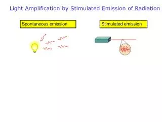
Stimulated Emission
Stimulated Emission. Spontaneous Emission · Excited States are metastable and must decay · Excited States have lifetimes ranging from milliseconds (10 -3 s) to nanoseconds (10 -9 s). Stimulated Emission : through collisions emitted photon

Stimulated Emission
E N D
Presentation Transcript
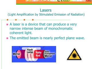
Stimulated Emission Spontaneous Emission · Excited States are metastable and must decay · Excited States have lifetimes ranging from milliseconds (10-3 s) to nanoseconds (10-9 s) Stimulated Emission: through collisions emitted photon causes other excited atoms to decay in phase • Faster emission than spontaneous • Emitted Photons are indistinguishable LASER: Light Amplification by Stimulated Emission Radiation
Stimulated Emission Rate: Absorption Rate: Number of atoms or molecules in lower energy level (Unit: per cm3) Number of atoms or molecules in lower energy level (Unit: per cm3) -σ12FN1 -σ21FN2 Absorption Cross-Section Units → cm2 Photon Flux Units → #/cm2sec Stimulated emission Cross-Section Units → cm2 (typical value ~ 10-19 to 10-18 cm2) Photon Flux Units → #/cm2sec
Stimulated Emission Rate: Absorption Rate: Number of atoms or molecules in lower energy level (Unit: per cm3) Number of atoms or molecules in lower energy level (Unit: per cm3) -σ12FN1 -σ21FN2 Absorption Cross-Section Units → cm2 Photon Flux Units → #/cm2sec Stimulated emission Cross-Section Units → cm2 (typical value ~ 10-19 to 10-18 cm2) Photon Flux Units → #/cm2sec Einstein showed: σ12 = σ21
Population Inversion: is the condition for light amplification through stimulated emission. Population inversion is not achievable through direct excitation in a two-level system.
http://www.olympusconfocal.com/java/stimulatedemission/index.htmlhttp://www.olympusconfocal.com/java/stimulatedemission/index.html Lasing begins as fluorescence
Need at least a three-level system R1 and R2 are the external “pump” rates. 1/20 is spontaneous emission rate 2→0 1/21 is spontaneous emission rate 2→1 1/1 is spontaneous emission rate 1→0 1/2= 1/ 21 + 1/20 2→(anything)
= 0 = 0
Four Level System is Most Common for Lasing E3-E2 radiationless decay 10-12 E2-E1 spontaneous lifetime of 10-6 E2-E1 stimulated emission of 10-9 E1-E0 radiationless decay 10-12
Pump Gain Gain region No absorption Below energy gap Loss region 0 Log(Iout/Iin) Photon Energy Absorption
Pump So What Is LASER? cavity output • Population inversion in lasing medium • Laser cavity to create the resonance amplification Gain from the medium > loss in the optics of the cavity
Laser Cavity Laser Cavity is also a Fabry-Perot optical resonator Not too different from the soap bubble FSR=/ = / 2nL or = c / 2nL : frequency c:speed of light n: refractive index L: cavity length
For an optical cavity of 20 cm emitting visible laser light at 500nm (blue) the number of integer wavelengths between the two mirrors would be Lines adjacent to the 500nm line are very close: 500.0013 nm 499.9987 nm Each line allowed by the cavity is a longitude mode.
Propagate ? Cross-section
Transverse Modes Low-order axisymmetric resonator modes Low-order Hermite-Gaussian resonator modes A single mode (such as TEM00) maintain beam cross-section shape during propagation
Gaussian Beam Propagation Near Field Far Field Beam waist • Light is a wave and diffract. It is therefore impossible to have a perfectly collimated beam. • If a Gaussian TEM00 laser-beam wavefront were made perfectly flat at some plane, it would quickly acquire curvature and begin spreading.
R -> z if z >> 0 At which point Gaussian beam looks like a point source. w = w0 if z << w02/ zR If = 500nm w0 = 2mm zR = 25.12 m zR also called Raleigh range R: wavefront curvature z: propagation distance w: Beam width defined as the width at 1/e (13.5%) of the peak intensity. w0: Beam width at beam waist.
Beam Quality For a theoretical single transverse mode Gaussian beam, the value of the waist radius–divergence product is: For any real laser beam: M2 is a dimensionless parameter to describe how “clean” is the mode of the laser beam, i.e., how close is it to a true Gaussian beam. Very good quality laser beam from low power He-Ne laser can have a M2 ~1.05. Most lasers does not have such ideal beam.
Embedded Gaussian • A mixed-mode beam: • Has a waist M (not M2) times larger than the embedded Gaussian. • Will propagate with a divergence M times greater than the embedded Gaussian • Has the same curvature and Raleigh range.
Mode Control • Larger (therefore higher order) modes are easier to get into lasing condition, because it goes through more active medium. • Aperture is commonly used to increase the loss for larger modes, so that only TEM00 mode is allowed to survive. • In many lasers, the limiting aperture is provided by the geometry • of the laser itself.
Some Common Lasers To build a laser, you need • Two Mirrors • Gain Medium • Pump
Nd:YAG • Four level laser • Host solid is single crystal YAG: yttrium aluminum garnet Y3Al5O12 • Optically active atoms Nd. Only <1% of the Medium. • Useful for cw operation, becauseYAG has high thermal conductivity and can handle a lot of heat. • Also useful for pulsed operation
Ar Ion Laser • One electron gets pulled off of one atom. • In the large field, the electron gets accelerated and impacts other atoms, knocking off other electrons. • A current of electrons is now flowing; the positive ions also cause a current. • Multiple electron collisions pump the Ar+, which emit light 400-500 nm • Very inefficient. 0.03%
Semiconductor Laser Mobile electrons Mobile holes
A better band picture • Many-state system • Optical transition reserves k • Population inversion easily achievable k
P-N Junction P type N type Emission Hole Injection Electron Injection - - - - + + + + N type P type
Small size • Very small cavity, large mode spacing. • Very efficient: ~50% efficiency • Most band gap is small, so emit IR light (shortest wavelength at ~760nm) • Can easily form arrays to increase total power output. • Mostly used as pump laser in microscopy applications.
Common Continuous Wave (CW) Lasers for Microscopy Argon UV (cw) 364 nm Argon Vis 488, 514 nm (458, 477 nm) Argon-Krypton 488, 568, 647 nm He-Ne 633 nm (laser pointer) DPSS laser 532 nm, 565 nm Not tunable Dye lasers are tunable and covers broad spectrum, but very difficult to operate. None appropriate for 2-p absorption, wrong colors, low power
Wide Field vs Confocal Fluorescence Imaging Confocal Greatly reduces Out of focus blur Wide-field Brighter but No sectioning
More examples widefield confocal pollen medulla muscle
Epi-illumination widefield is form of Kohler Illumination: Objective is also condenser Lamp or laser lens detector Detect at 90 degrees Split with dichroic mirror
Confocal detection with 3 dimensional scanning Image one plane, Move focus
Confocal Aperture • Decreasing the pinhole size rejects more out of focus light, therefore improving contrast and effective z resolution. • Decreasing the pinhole will increase x,y resolution (1.3x widefield) • Decreasing pinhole size decreases the amount of the Airy disk that reaches the detector. This results in less light from each point being collected • Generally, collecting the diameter of 1 Airy disk is considered optimal. This collects about 85% of light from a sub-resolution point. Limits: Open pinhole: nearly widefield resolution (still some confocality) Closed: no image
Signal, S/N (out of focus) opposite trends Closed: better axial sectioning, but no photons for contrast Open: no sectioning, lots of photons
Confocal Aperture • ALIGNMENT OF APERTURES IS CRITICAL • X, Y alignment : Different wavelengths focus at different lateral position. • Lateral color aberrations can be important for multi-color imaging • (multiple dyes with multiple lasers) • Z alignment: Different wavelengths focus at different depths in image plane. Chromatic aberrations can be important. Need well-corrected lenses
Intermediate Optical Path of Confocal Microscope • Requirements: • Laser path has same conjugate planes • as intermediate, detector, eyepieces • 2) Laser Scans undeviated around pivot point: • Stays on optical axis • 3) Back aperture of objective is always filled • For highest resolution • Consequences: • Pupil transfer lens 50-100 mm fl to fill lens • Max scan angle ~7 degrees while • still filling lens • 3) Position of pupil lens is critical • for parfocality with Kohler illumination • Brightfield and epi-fluorescence
Scanning Galvanometers Much faster than stage scanning (1000x) Point Scanning Mirrors on magnets x y Laser out To Microscope Laser in
X = 128 t = 0 Y = 128 t = 0.25 sec Scan Time Issues Typical scan rate 1s /scan 512X 512 Faster is not stable with galvos, but can reduce #pixels t = 0 X = 512 Y = 512 t = 1 sec