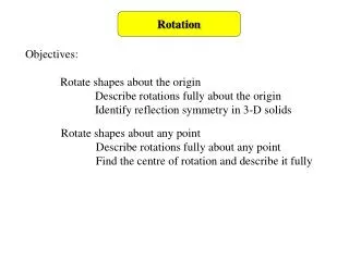
PHY1012F ROTATION
PHY1012F ROTATION. Gregor Leigh gregor.leigh@uct.ac.za. ROTATION OF A RIGID BODY. Extend the ideas, skills and problem-solving techniques developed in kinematics and dynamics (particularly with regard to circular motion) to the rotation of rigid bodies.

PHY1012F ROTATION
E N D
Presentation Transcript
PHY1012FROTATION Gregor Leighgregor.leigh@uct.ac.za
ROTATION OF A RIGID BODY ROTATION OF A RIGID BODY • Extend the ideas, skills and problem-solving techniques developed in kinematics and dynamics (particularly with regard to circular motion) to the rotation of rigid bodies. • Calculate torques and moments of inertia. • Apply appropriate mathematical representations (equations) in order to solve rotation problems. Learning outcomes:At the end of this chapter you should be able to…
ROTATION OF A RIGID BODY ROTATIONAL KINEMATICS • Rigid body model: • A rigid body is an extended object whose shape and size do not change as it moves. Neither does it flex or bend. Types of motion: Translational motion: Rotational motion: Combination motion:
ROTATION OF A RIGID BODY ANGULAR ACCELERATION s = r s vt = r at = r A body’s angular acceleration, , is the rate at which its angular velocity changes. Units: [rad/s2]
ROTATION OF A RIGID BODY ANGULAR VELOCITY and ANGULAR ACCELERATION – + > 0 < 0 + faster slower > 0 > 0 Angular velocity, > 0 < 0 – slower faster < 0 < 0
(rad/s) 3 0 3 6 9 12 • t (s) –3 (rad/s2) ½ 0 • t (s) 3 6 9 12 –½ – ROTATION OF A RIGID BODY VELOCITY GRAPHS ACCELERATION GRAPHS Angular acceleration is equivalent to the slope of a -vs-tgraph. Eg: A wheel rotates about its axle… For the first 6 s the is slope acceleration
(rad/s) 3 0 3 6 9 12 • t (s) –3 (rad/s2) ½ 0 • t (s) 3 6 9 12 –½ – ROTATION OF A RIGID BODY VELOCITY GRAPHS ACCELERATION GRAPHS Angular acceleration is equivalent to the slope of a -vs-tgraph. Eg: A wheel rotates about its axle… For the last 6 s the is slope acceleration
ROTATION OF A RIGID BODY KINEMATIC EQUATIONS • The following equations apply for constant acceleration: vf = vi + at f = i + t xf = xi + vit + ½a(t)2 f = i + it + ½(t)2 vf2= vi2 + 2ax f2= i2 + 2
ROTATION OF A RIGID BODY CENTRE OF MASS • While the various points on a flipped spanner describe different (complicated) trajectories, one special point, the centre of mass, follows the usual, simple parabolic path. The centre of mass (CM) of a system of particles… • is the weighted mean position of the system’s mass; • is the point which behaves as though all of the system’s mass were concentrated there, and all external forces were applied there; • is the point around which an unconstrained system (i.e. one without an axle or pivot) will naturally rotate.
ROTATION OF A RIGID BODY CENTRE OF MASS • To find the centre of mass of two masses… • x m2 • xCM m1 • x2 • place the masses on an x-axis, with one of the masses at the origin; • apply the formula: • x1 = 0 In general, for many particles on any axis: And for a continuous distributionof mass in which mi = M:
ROTATION OF A RIGID BODY TORQUE • The rotational analogue of force is called torque, . Torque may be regarded as… • the “amount of turning” required to rotate a body around a certain point called an axis or a pivot; • the effectiveness of a force at causing turning. E.g. To push open a heavy door around its hinge (as seen from the top) requires a force applied at some point on the door. Consider the effectiveness of each of the (equal) forces shown… hinge
r ROTATION OF A RIGID BODY TORQUE Three factors determine the amount of torque achieved: • magnitude of the applied force; • distance between the point of application and the pivot; • angle at which the force is applied. Only the tangential component of the applied force produces any turning… • y Ft = Fsin radial line Fr = rFt point of application Hence: rFsin • x Units: [Nm] ( joule!) pivot
ROTATION OF A RIGID BODY TORQUE • Torque can also be defined as the product of the force, F, and the perpendicular distance between the pivot and the line of action of the force, d, known as the torque arm, moment arm, or lever arm: | | = dF torque armd = rsin Torque… • is positive if it tries to rotate the object anticlockwise about the pivot; negative if rotation is clockwise; • must be measured relative to a specificpivot point. r line of action • x pivot
ROTATION OF A RIGID BODY NET TORQUE • Several forces act on an extended object which is free to rotate around an axle. The axle prevents any translational movement, so… axle And the net torque is given by: net = 1 + 2 + 3 + …=i ( causes no torque since it is applied at the axle.)
CM pivot • x • xCM • 0 ROTATION OF A RIGID BODY GRAVITATIONAL TORQUE • For an object to be balanced, its centre of mass must lie either directly above or directly below the point of support. centre of mass If this is not so, the body’s own weight, acting through its centre of mass (as if all its mass were concentrated there), causes a net torque due to gravity: grav = –MgxCM • Mg where xCM is the distance between the centre of mass and the pivot.
ROTATION OF A RIGID BODY COUPLES • Rotation without translation is achieved by the application of a pair of equal but opposite forces at two different points on the object. d1 d2 pivot |net | = d1F + d2F = (d1 + d2)F |net | = lF (sign by inspection) l Notes: • The pivot is immaterial – a couple will exert the same net torque lF about any point on the object. • Unless the rotation is constrained to act around a specific pivot, it will occur around the body’s centre of mass.
ROTATION OF A RIGID BODY ROTATIONAL DYNAMICS • Newton II (linear): • Force causes linear acceleration. • Linear acceleration is “limited” by inertial mass. A rocket is constrained to move in a circle by a lightweight rod… • y Ft Fr rod pivot • x Ft = mat Ft = mr rFt = mr2 = mr2 Newton II (rotational): • Torque causes angular acceleration. • Angular acceleration is “limited” by the particle’s rotational inertia, mr2, about the pivot.
ROTATION OF A RIGID BODY ROTATIONAL INERTIA m2 • A rotating extended object can be modelled as a collection of particles, each a certain distance from the pivot. m1 r2 m3 r1 r3 pivot The body’s rotational inertia… • is also known as its moment of inertia, I; • is the aggregate of the individual (mr2)’s: • gives an indication of how the mass of the body is distributed about its axis of rotation (pivot); • is the rotational equivalent of mass. I = m1r12 + m2r22 + m3r32 + … = miri2 Thus:
ROTATION OF A RIGID BODY ROTATIONAL DYNAMICS • Summary of corresponding quantities and relationships: force Fnet torque net inertial mass m moment of inertia I acceleration a angular acceleration Newton II Fnet = ma Newton II net = I
MOMENTS OF INERTIA For an extended system with a continuous distribution of mass, the system is divided into equal-mass elements, m. Then, by allowing these to shrink in size, the moment of inertia summation is converted to an integration: • y • x PHY1012F ROTATION OF A RIGID BODY m For complex distributions of mass, r is usually replaced by x and y components… r y x pivot …and, before integration, dm is replaced by an expression involving a coordinate differential such as dx or dy. 20
R MOMENTS OF INERTIA • For simple, uniform distributions of mass, however, the integration can be trivial. E.g. in a wheel, or hoop, where all the mass lies at a distance R from the axis… becomes , where the integral is simply the sum of all the mass elements, i.e. the total mass, M, of the wheel. So for open wheels (hoops) I = MR2. In practice, the rotational inertias of certain common shapes (of uniform density) are looked up in tables…
ROTATION OF A RIGID BODY PARALLEL AXIS THEOREM • Moments of inertia are always calculated/stated with respect to a specific axis of rotation. However (assuming the moment of inertia for rotation around the centre of mass is known), the moment of inertia around any off-centre rotation axis lying parallel to the axis through the centre of mass can be found using the parallel-axis theorem: CM d M (mass) I = ICM + Md2
ROTATION OF A RIGID BODY ROTATION ABOUT A FIXED AXIS • Model the object as a simple shape. • Identify the axis around which the object rotates. • Draw a picture of the situation, including coordinate axes, symbols and known information. • Identify all the significant forces acting on the object and determine the distance of each force from the axis. • Determine all torques, including their signs. • Apply Newton II: net = I. (I-values from tables and the parallel-axis theorem.) • Use rotational kinematics to find angular positions and velocities. • Problem-solving strategy:
x • 0 ROTATION OF A RIGID BODY ROTATION ABOUT A FIXED AXIS A 70 g metre stick pivoted freely at one end is released from a horizontal position. At what speed does the far end swing through its lowest position? pivot • M = 0.07 kg 1-3. Model the stick as a uniform rod rotating around one end, and draw a picture with pivot, x-axis and data.
ROTATION OF A RIGID BODY ROTATION ABOUT A FIXED AXIS A 70 g metre stick pivoted freely at one end is released from a horizontal position. At what speed does the far end swing through its lowest position? • x • xCM = 0.5 m • 0 pivot • M = 0.07 kg • Mg • Identify all significant forces acting on the object and determine the distance of each force from the axis.
ROTATION OF A RIGID BODY ROTATION ABOUT A FIXED AXIS A 70 g metre stick pivoted freely at one end is released from a horizontal position. At what speed does the far end swing through its lowest position? • x • xCM = 0.5 m • 0 pivot • M = 0.07 kg • Mg • –ve grav = –MgxCM = –0.07 9.8 0.5 = –0.34 Nm • Determine all torques, including their signs.
ROTATION OF A RIGID BODY ROTATION ABOUT A FIXED AXIS A 70 g metre stick pivoted freely at one end is released from a horizontal position. At what speed does the far end swing through its lowest position? net = I • x • Mg • M = 0.07 kg pivot grav = –0.34 Nm = –15 rad/s2 • Apply Newton II: net = I.
ROTATION OF A RIGID BODY ROTATION ABOUT A FIXED AXIS A 70 g metre stick pivoted freely at one end is released from a horizontal position. At what speed does the far end swing through its lowest position? pivot f2= i2 + 2 i= 0 radi= 0 rad/s • You canNOT use rotational kinematics to solve this problem! Why not? f2= 0 + 2(–15)(–0.5 ) = –15 rad/s2 vt = r f= –0.5 radf= ? vt = –6.8 1 = 6.8 m/s • Use rotational kinematics to find angular positions and velocities. • (Not this time!)
CONSTRAINTS DUE TO ROPES and PULLEYS Provided it does not slip, a rope passing over a pulley moves in the same way as the pulley’s rim, and thus also objects attached to the rope. PHY1012F ROTATION OF A RIGID BODY rim acceleration = ||R rim speed = ||R non-slipping rope R vobj= ||R As before, the constraints are given as magnitudes. Actual signs are chosen by inspection. aobj= ||R 29
y m1 m1 • x m2 m2 ROTATION OF A RIGID BODY T2 T1 T3 • Two blocks are connected by a light string which passes over two identical pulleys, each with a moment of inertia I, as shown. Find the acceleration of each mass and the tensions T1 , T2 and T3. T3 T2 n2 T2 T1 n1 +ve –ve w T3 T1 w m1g m2g +ve –ve • F1y = T1– m1g = m1a(1) • F2y = T3– m2g = –m2a(2) • net = T1R–T2R = –I(3) • net = T2R–T3R = –I(4)
m1 m2 ROTATION OF A RIGID BODY T2 • F1y = T1– m1g = m1a(1) T1 T3 • F2y = T3– m2g = –m2a(2) • y • net = T1R–T2R = –I(3) • x • net = T2R–T3R = –I(4) • (3) + (4):T1R–T3R = –2I • (1)–(2):T1–T3+ m2g– m1g = m1a + m2a • …etc
ROTATION OF A RIGID BODY RIGID BODY EQUILIBRIUM • Problem-solving strategy: • Model the object as a simple shape. • Draw a picture of the situation, including coordinate axes, symbols and known information. • Identify all the significant forces acting on the object. • Choose a convenient pivot point and determine the moment arm of each force from it. • Determine the sign of each torque around the pivot. • Write equations for Fx = 0; Fy = 0; net = 0; and solve.
y • x CM ROTATION OF A RIGID BODY RIGID BODY EQUILIBRIUM A 3-metre ladder leans against a frictionless wall, making an angle of 60° with the ground. What minimum coefficient of friction is needed to prevent the foot of the ladder from slipping? L 1-2. Model the ladder as a rigid rod, and draw a picture with axes, symbols and known information.
CM ROTATION OF A RIGID BODY RIGID BODY EQUILIBRIUM A 3-metre ladder leans against a frictionless wall, making an angle of 60° with the ground. What minimum coefficient of friction is needed to prevent the foot of the ladder from slipping? • y L • x 3. Identify all the significant forces acting on the object.
CM ROTATION OF A RIGID BODY RIGID BODY EQUILIBRIUM A 3-metre ladder leans against a frictionless wall, making an angle of 60° with the ground. What minimum coefficient of friction is needed to prevent the foot of the ladder from slipping? • y L d2 d1 pivot • x 4. Choose a convenient pivot point and determine the moment arm of each force from it.
CM ROTATION OF A RIGID BODY RIGID BODY EQUILIBRIUM –ve A 3-metre ladder leans against a frictionless wall, making an angle of 60° with the ground. What minimum coefficient of friction is needed to prevent the foot of the ladder from slipping? • y L d2 +ve d1 pivot • x 5. Determine the sign of each torque around the pivot.
CM ROTATION OF A RIGID BODY RIGID BODY EQUILIBRIUM –ve Fx = nw– fs= 0 (1) • y • Fy = nf– Mg = 0 (2) • net = d1w–d2nw = 0 (3) L • net = ½(Lcos60°)Mg – (Lsin60°)nw= 0 d2 +ve d1 pivot • x 6. Write equations for Fx= 0; Fy= 0; net= 0; and solve.
ROTATION OF A RIGID BODY ROTATION OF A RIGID BODY • Extend the ideas, skills and problem-solving techniques developed in kinematics and dynamics (particularly with regard to circular motion) to the rotation of rigid bodies. • Calculate torques and moments of inertia. • Apply appropriate mathematical representations (equations) in order to solve rotation problems. Learning outcomes:At the end of this chapter you should be able to…