Synchronous Rectifier in Forward Converter
Synchronous Rectifier in Forward Converter. Rectifier Circuit Rectifier Concept Synchronous Rectifier C -1 : RCD Clamp & Self - Driven SRs C -2 : Active Clamp & Self - Driven SRs C -3 : Control – Driven D. Power Loss Comparisons E. Efficiency Curve. A. Rectifier Circuit.


Synchronous Rectifier in Forward Converter
E N D
Presentation Transcript
Rectifier Circuit • Rectifier Concept • Synchronous Rectifier • C -1 : RCD Clamp & Self - Driven SRs • C -2 : Active Clamp & Self - Driven SRs • C -3 : Control – Driven • D. Power Loss Comparisons • E. Efficiency Curve
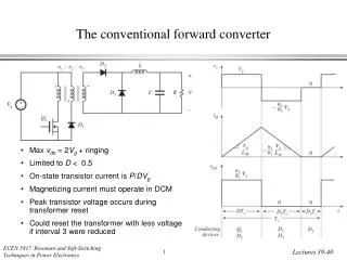
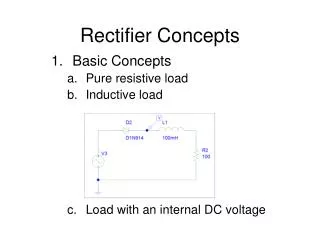
A. Rectifier Circuit Fig1 : Forward Converter with MOSFET Fig2 : Forward Converter with Diode
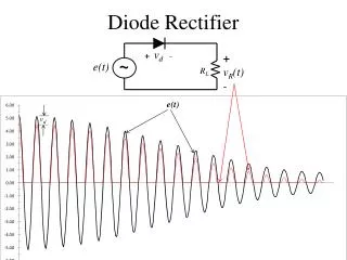
B. Rectifier Concept The switching losses caused by the reverse recovery current of the body - diode will be dependent of the carried current in the instant in the which the voltage between anode and cathode reverses become negative
C. Synchronous Rectifier C-1 RCD Clamp & Self – Driven SRs • Gate –Driver signal • Drain to Source voltage of primary switch • Secondary winding voltage • Current through SR2 • Current through SR3
C. Synchronous Rectifier C-2 Active Clamp & Self – Driven SRs • Gate –Driver signal • Drain to Source voltage of primary switch • Secondary winding voltage • Current through SR2 • Current through SR3
C. Synchronous Rectifier C-3 Control – Driven SRs • Gate –Driver signal • Drain to Source voltage of primary switch • Secondary winding voltage • Current through SR2 • Current through SR3
Converter efficiency Converter Efficiency ( For Schottky Rectifiers ) Converter Efficiency ( For Synchronous Rectifiers ) D. Power Loss Comparisons PO : Output Power Ploss : Total Loss ; PSH : Schottky Rectifiers Loss PSR : Synchronous Rectifiers Loss
Schottky Power Loss Self – Drivens SR Loss Control – Drivens SR Loss D. Power Loss Comparisons
Efficiency ( RCD Self –Driven SRs) D. Power Loss Comparisons Efficiency ( Active Self –Driven SRs) Efficiency ( Control –Driven SRs) VD = VSH = Body Diode Voltage ; Ddead = dead time duty cycle ; Ddelay = delay time duty cycle
E. Efficiency Curve Ddelay ≈ 0
E. Efficiency Curve Ddead ≈ 0.2