Comprehensive Guide to Hydraulic System Components and Assembly Diagrams
160 likes | 279 Vues
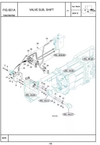
This detailed document covers essential components of hydraulic systems, including piping, valves, pumps, and control mechanisms. It provides visual representations and descriptions for each part, such as the gear pump assembly, filter suction, and various valves. The guide also details auxiliary valves, levers, and linkage mechanisms critical for effective operation. Each figure is annotated for easy identification, making it an invaluable resource for technicians and engineers involved in hydraulic systems design and maintenance.

Comprehensive Guide to Hydraulic System Components and Assembly Diagrams
E N D
Presentation Transcript
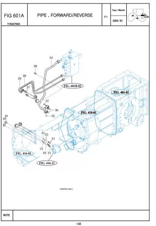
FIG 601A PIPE , FORWARD/REVERSE P1 198
FIG 601B VALVE SUB , MAIN P1 200
FIG 602 DRAWBAR ASSY P1 204
FIG 603A FILTER SUB, SUCTION P1 206
FIG 603B GEAR PUMP ASSY P1 208
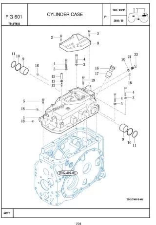
FIG 604 CASE , CYLINDER P1 210
FIG 605 ARM SUB, LIFT MAIN CONTROL VALVE SUB P1 212
FIG 606 POSITION & DRAFT LINK P1 214
FIG 607A AUX VALVE & FILTER SUB P1 216
FIG 607B LEVER SUB, AUX P1 194
FIG 607C POSITION & DRAFT LEVER P1 194
FIG 608A HITCH & 3-POINT LINK P1 218
FIG 608B HITCH & 3-POINT LINK P1 220
FIG 608C LOWER LINK & LIFT ROD P1 222
FIG 609 HYDRAULIC PIPE & HOSES P1 224
FIG 610 JOYSTICK P1 226