Download
1 / 29
290 likes | 308 Vues
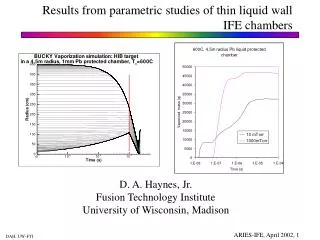
1. Liquid Wall Ablation under IFE Photon Energy Deposition 2. Flibe Properties from EoS. A. René Raffray and Mofreh Zaghloul University of California, San Diego ARIES Town Meeting on Liquid Wall Chamber Dynamics Hilton Garden Inn, Livermore, CA May 5-6, 2003.

E N D
1. Liquid Wall Ablation under IFE Photon Energy Deposition 2. Flibe Properties from EoS A. René Raffray and Mofreh Zaghloul University of California, San Diego ARIES Town Meeting on Liquid Wall Chamber Dynamics Hilton Garden Inn, Livermore, CA May 5-6, 2003
Physical Processes in X-Ray Ablation Energy Deposition & Transient Heat Transport x Induced Thermal- Spikes Fast Ions y z Mechanical Response Phase Transitions Slow Ions • Stresses and Strains and Hydrodynamic Motion • Fractures and Spall • Surface Vaporization • Heterogeneous Nucleation • Homogeneous Nucleation (Phase Explosion) Ablation Processes Expansion, Cooling and Condensation Surface Vaporization Liquid Film X-Rays Impulse Spall Fractures Impulse Phase Explosion Liquid/Vapor Mixture
High Photon Heating Rate Could Lead to Explosive Boiling • Effect of free surface vaporization is reduced for very high for heating rate (photon-like) • Vaporization into heterogeneous nuclei is also very low for high heating rate Ion-like heating rate Photon-like heating rate • Rapid boiling involving homogeneous nucleation leads to superheating to a metastable liquid state • • The metastable liquid has an excess free energy, so it decomposes explosively into liquid and vapor phases. • - As T/Ttc increases past 0.9, Becker- Döhring theory of nucleation indicate an avalanche-like and explosive growth of nucleation rate (by 20-30 orders of magnitude) From K. Song and X. Xu, Applied Surface Science 127-129 (1998) 111-116
Analysis Based on Photon Spectra for 458 MJ Indirect Drive Target (25%) (1%) • High photon energy for indirect drive target case (25% compared to 6% ion energy)) • More details on target spectra available on ARIES Web site: http://aries.ucsd.edu/ARIES/
Photon Energy Deposition Density Profile in Flibe Film and Explosive Boiling Region (for Rchamber=6.5m) Sensible energy based on uniform vapor pressure following photon passage in chamber and including evaporated Flibe from film Cohesion energy (total evaporation energy) 0.9 Tcritical Sensible energy (energy to reach saturation) Explo. boil. region Evap. region 2-phase region 4.1 2.5 10.4 Bounding estimates of thermally-induced aerosol source term from photon energy deposition: (1)Upper bound: the whole 2-phase region; (2)Lower bound: explosive boiling region
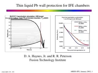
Photon Energy Deposition Density Profile in Pb Film and Explosive Boiling Region (for Rchamber=6.5m) Cohesion energy (total evaporation energy) 0.9 Tcritical Sensible energy (energy to reach saturation) Explo. boil. region Evaporated region 2.5 3.9 1.9 2-phase region
Explosive Boiling Results for Rchamber=3.5 m • Explosive Boiling Ablated Thickness for: • FlibePb • Rchamber= 6.5 m 4.1 mm 2.5 mm • Rchamber= 3.5 m 10.9 mm 3.83 mm
Mechanical Response to Induced Shock • • Rapid increase in internal energy due to x-ray energy deposition and ablation impulse creates high pressure within the material • - The induced shock wave propagates to the wall, gets reflected back to the free surface where a rarefaction wave is produced (creating tensile stresses) and propagates back through the material. The process is repeated. • - If the magnitude of the rarefaction wave is greater than the tensile strength of the material, fracture or spall will occur establishing a new surface. • • Evolution of spall in a body subject to transient stresses is complex • - Material dependent: brittle, ductile or liquid • - Small perturbations can lead to opening of voids and initiation of spall process • - A reasonable prediction of the dynamic spall strength, time to failure, and some measure of the nominal fragment size created in the spall event are needed to characterize the spall process • - An upper bound theoretical spall strength can be derived from intermolecular potential
Theoretical spall strength, Pth, given by minimum of P(v): Theoretical (Maximum) Spall Strength Provides an Upper Bound Estimate in the Absence of Appropriate Spall Data • Based on intermolecular potential reflecting dependence on cohesive energy and bulk modulus with inherent energy balance - Using a three-parameter potential such as the Morse potential - The cold pressure is given by: Ucoh= Specific cohesive energy v = 1/ = Specific volume v0 = Specific volume at zero pressure a=(2v0 Ucoh / B0 )1/2 B0 = Bulk modulus
Spall Strength is Highly Temperature Dependent • Using the Soft Sphere EOS to Estimate Temperature-Dependent Spall Strength • n, m, Q, , and are adjustable parameters to satisfy the available experimental data • N: Number of molecules, • V: Specific volume, • = N 3 / (21/2) V, : the sphere diameter, • Cn: FCC Madelung constant. • Theoretical spall strength is then calculated from:
Parameters of Different IFE Reactor Design Studies &Pressure Pulse Profile * X-ray and debris ** Ablated material velocity ~ sonic velocity ~ 586/2094 m/s for Pb/Flibe at Tcrit (~5100/4500 K) • The pressure wave is steady (no change in shape) • Parameters of different IFE reactor design studies and the present study are comparable • Osirus profile scaled according to the relative impulses and used for the present analysis.
2. Pfree-surface= Pchamber and the pressure pulse arriving at the free boundary must be reflected back as a tensile wave 3. If the net tensile stress > the spall strength of the material, rupture occurs establishing a new surface 1. For a perfectly stiff wall, the pressure wave is reflected from the wall and returns to the free surface as a pressure pulse Illustration of Spalling Following a Pressure Wave Propagation in the Flibe Layer on a Perfectly Stiff Wall 2000 kg/m3, Cs 3300 m/s, Tin = 885.7 K, Pth = -1.887 GPa Spalled Thickness 2.1 µm & Spall Time (t3 – t1) 16.9 ns Spall time from the beginning of the pressure pulse = 2 L/Cs+ (t3-t1) 200 ns for a 0.3 mm flibe layer
BUT No Wall is Perfectly Stiff ! E.g. For Pb/SiC and 3.5 m Cavity Radius = -0.541 • Pressure wave is reflected as a reduced tensile wave. • The max. pres., Pmax, of the reflected wave = -6.67 GPa • Spall tensile strength, Pth, = -1.875 GPa • Pmax>Pth Spall occurs (at 0.94 µm from the wall) In principle, combination of liquid and structural material can be chosen to eliminate or minimize spalling A pressure pulse with initial pressure P0 will be reflected at the mismatched interface with a new pressure, P where: With the acoustic impedance Z = Cs
Spallation Analysis for Different Proposed Liquid/Wall Combinations
Summary of Study of Wall Ablation Mechanisms as Aerosol Source Term • Integrated effect of liquid wall thermal and mechanical responses to X-ray energy deposition to provide bounding estimates of ablation as source term for aerosol analysis - First principle consideration - Ablation depths of liquid wall from explosive boiling and spalling - Spall strength of materials as compared to anticipated IFE shocks - Acoustic impedances of structural material and liquid can be chosen to avoid or minimize spalling • Some key remaining questions - Form (vapor conditions, size and distribution of liquid droplets) of the removed material? - What happens to the spalled material (not enough energy to push it out…where does it go?) - Spall time scale
Flibe Properties from EoS M. Zaghloul University of California, San Diego ARIES Town Meeting on Liquid Wall Chamber Dynamics Hilton Garden Inn, Livermore, CA May 5-6, 2003
Flibe Thermodynamic Properties Temperature Liquid + Vapor Tcrit ~ 4500 K Vapor chemical decomposition of molecules T ~ 1 eV Plasma multiple ionization • The soft-sphere equation of state for liquid flibe takes into account the dependence on and T(*). • Vapor pressure correlations from ORNL & Olander et al., Fusion Technology,41, 141 (2002). (Revisited) • Chemical equilibrium codes that use data from JANAF tables are used (e.g. the computer code STANJAN, Stanford Univ.) • Fitted equations of state for flibe gas(**). • Inaccuracies include • - Use of Post-Jensen ionization data calculated from the Corona equilibrium (valid only for extremely low densities and very high temperatures-optically thin plasma-and show no dependence on density). • - Post-Jensen data give no information on the individual populations needed for the internal energy computation and so further approximations have to be made. • - No Coulomb corrections. • - No excitation energies included in the computations of internal energies. Improved Modeling and Computations in the High-Temperature Region are Needed (*) Xiang M. Chen , Virgil E. Schrock, and Per F. Peterson “ The soft-sphere equation of state for liquid Flibe,” Fusion Tech. 21, 1525 (1992). (**) Xiang M. Chen, Virgil E. Schrock, and Per F. Peterson, “Fitted Equation of State for Flibe Gas,” Fusion Technology 26, 912 (1994).
Flibe Vapor Pressure and Stability of LiBeF3(*)(*) Mofreh Zaghloul, D. K. Sze, A. R. Raffray, “Thermo-physical Properties and Equilibrium Vapor Composition of Lithium-Fluoride Beryllium-Fluoride (LiF/BeF2) Molten Salt ,” 15th Topical Meeting on the Technology of Fusion Energy, TOFE, Washington, DC, Nov. 2002. • Based on previous experimental results by Buchler and Stauffer(***),Olander et al(**) assumed a LiBeF3 contribution of ~10% to flibe vapor, and estimated the LiBeF3 vapor pressure based on a negative energy of formation (G0 < 0) • However, from Knack et al. and using NIST-JANAF tables, G0 for LiBeF3 0 for T 555 K (Meta-stable) • Accordingly, Olander et al. overestimated the vapor pressure of LiBeF3 by ~ 30 orders of magnitude • However the effect on their estimation of the overall vapor pressure of flibe is much smaller since LiBeF3 contribution was assumed to be ~10% (**) Olander et al., Fusion Technology,41, 141 (2002). (***) O. KNACKE, O. KUBASCHEWSKI and K. HESSELMANN (Eds.), Thermochemical Properties of Inorganic Substances I, second edition, Springer-Verlag, Berlin, Germany (1991).
Proposed Correlation for Flibe Vapor Pressure Over a Wide Range of Temperature One can combine the values computed for flibe vapor pressure using thermo-chemical data from NIST-JANAF tables in the low temperature region to ORNL measurements (adequately accurate for T >1000 C) and use a best fit to obtain a correlation valid over a wide range of temp.
V- Coulomb Corrections IV- Electro-neutrality. Terminated Partition Function Continuum Lowering(***) Ionization Equilibrium and Thermodynamic Functions(*)(*)Mofreh R. Zaghloul, “A consistent model for the equilibrium thermodynamic functions of partially ionized Flibe plasma with Coulomb Corrections,” Physics of Plasmas, 10, No. 2 (2003) 527-538. Assumptions I- Fully-Dissociated Flibe-Gas (T> 1 eV) (Mixture of Monatomic Gases); II- Local Thermodynamic Equilibrium LTE (Validity Criterion by Fujimoto(**)) III- No Nuclear Reactions (Constant Number of Heavy Particles ) nH= Const.; (**) T. Fujimoto et al, Phys. Rev. A 42, 6588 (1990). (***) W. Ebeling et al, Theory of Bound States and Ionization Equilibrium in Plasmas and Solids (Akademic-Verlag, 1976)
5- Adiabatic exponent 6- Sound Speed 4- Enthalpy Thermodynamic Relations 1- Pressure 2- Internal energy 3- Contribution of excitation energies of ion i of element j to internal energy The most rigorous expressions for thermodynamic functions have been used
Results of Detailed Composition & Average Ionization State • The lower the density the lower recombination rate, and the higher <Z>. • The lower the density the more prominent is the step-like structure of the <Z>. • At very high T, the value of <Z> approaches its expected value of a fully-dissociated, fully-ionized flibe-plasma , <Z> = 6.57. • As the temperature increases, the molar fractions of neutral species (Li, Be, and F) decrease monotonically as a result of the progressive ionization. • With further increase of the temperature, higher ionized ionic species appear on the expense of lower-fold ionized species.
Results for Flibe Pressure & Internal Energy • Substantial deviation from the ideal-gas linear behavior. • Ionization and Coulomb interactions among charged particles are responsible for the deviation in the pressure curves, while for internal energy another contribution comes from excitation.
Results for Flibe Specific Heat, Adiabatic Exponent & Sound Speed • Non-linearity characteristics of high temperature plasma are most prominent. • At very high T, Cp increases to its expected value of a fully-dissociated, fully-ionized flibe-plasma (Cp = 1.1138104 J/kg K) and so for the other properties.
ResultsValidity of LTE Assumption & Effect of Coulomb Corrections • <Z> is the most affected parameter at low temperatures. • Percentage relative differences of other parameters at the same density are bounded within 15 %. • LTE assumption is applicable for densities 0.001 kg/m3 for the temperature range shown.
Comparison with Chen’s et al Results (*).(*) Xiang M. Chen, Virgil E. Schrock, and Per F. Peterson, Fusion Technology 26, 912 (1994). • Differences of up to ~ 65% • Differences of up to ~ 150%
Optical Characteristics of Flibe Multi-Frequency Absorption Coefficient In the evaluation of the multi-frequency absorption coefficient, • Molecular absorption is neglected (the plasma temperature is considered to be sufficiently high > 1 eV that the plasma is fully dissociated); • Photon energies are low enough (< 1MeV) that high-energy absorption processes such as pair production and nuclear photoabsorption can be ignored; • Only electronic transitions in the field of the ions are considered (bound-bound, bound-free, and free-free) as these constitute the major absorption processes for most conditions of interest.