Download
1 / 11
110 likes | 277 Vues
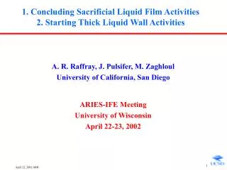
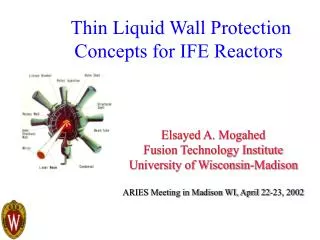
Vapor Conditions Including Ionization State in Thick Liquid Wall IFE Reactors. C/C HIB target 50cm, 90cm radius voids (1Torr FLiBe vapor) 100cm thick liquid FLiBe Initial Temperature: 600C. Presented by D. A. Haynes, Jr. for the staff of the Fusion Technology Institute

E N D
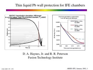
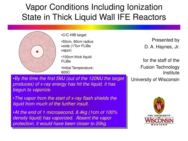
Vapor Conditions Including Ionization State in Thick Liquid Wall IFE Reactors • C/C HIB target • 50cm, 90cm radius voids (1Torr FLiBe vapor) • 100cm thick liquid FLiBe • Initial Temperature: 600C Presented by D. A. Haynes, Jr. for the staff of the Fusion Technology Institute University of Wisconsin • By the time the first 5MJ (out of the 120MJ the target produces) of x-ray energy has hit the liquid, it has begun to vaporize. • The vapor from the start of x-ray flash shields the liquid from much of the further insult. • At the end of 1 microsecond, 8.4kg (1cm of 100% density liquid) has vaporized. Absent the vapor protection, it would have been closer to 20kg.
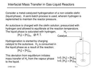
“Heat capacity” EOS Advantages: Latent heats easily incorporated Bookkeeping Disadvantages: Inconsistent EOS/Opacity as zone moves from wall to vapor. No shock tracking within wall. Only current surface zone can vaporize “Plasma” EOS Advantages: Consistent EOS/Opacity Shock tracking within the wall “Buried” “evaporation” Disadvantages Currently: no latent heats in FLiBe tables Bookkeeping (plasma/wall distinguished only by density) BUCKY can treat “walls” in two modes, each of which has advantages and disadvantages
Soon after 1 microsecond, the shock from the blowoff will interact with the shock from center of the chamber, and we should hand off to a higher dimensional code which encompasses aerosolization and dynamic jet location.
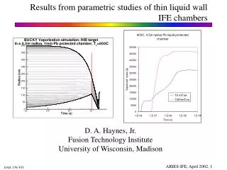
The shocks rattling around the central void render 1 dimensional simulations suspect after 20 microseconds. • For an initial void radius of 90cm, the outward moving shock interacts with the wall blowoff around 10 microseconds. • Note the outer wall movement at late times.
As the wall blowoff moves in the chamber, it cools but remains significantly ionized as aerosolization initiates. Initially in vapor Initially in “wall” Does this ionization inhibit aerosol formation?
A narrow band of the blowoff plasma shields the rest of the liquid from the target emissions, slowly re-radiating and causing the rest of the wall to simmer. • For FLiBe, with its simple atomic physics, EOS/Opacity tables can be created in DCA/NLTE with accurate emissivity values. • For Pb, LiPb, LiSn, an alternative procedure can be employed. BUCKY simulation of 90cm radius, 1 Torr FLiBe void, wall at 600C (ns)
Under jj coupling, the initial • configuration is split • into: Cowan’s Code RSSUTA • For each subconfiguration, • there are two transitions: • Spin orbital integrals are greater than Slater integrals Evolution of the Transition Patterns from Low Z to High Z Transition: (Examples from C. Bauche-Arnoult, et al., Phys. Rev. A, 31, 2248, 1985)
Path forward: prompt chamber response for thin and thick liquid wall protected IFE chambers • What needs to be done? • Identification of variables for operating window studies • Combination of validated, relevant prompt physics simulation (rad. transport, ionization, evaporation) with validated, relevant aerosol model, and validated, relevant 3-d hydrodynamics code. • Validation of combination! • Addition of latent heat to plasma modeling of liquid wall phenomena (combine the best parts of BUCKY’s split personality) • Post-vaporization/ionization chemistry before/during/after aerosolization. • Comparison of initial vaporization phase in spherical (chamber-centric) and cylindrical (jet-centered) geometries
Path forward: prompt chamber response for thin and thick liquid wall protected IFE chambers • Importance of results to feasibility of HIB concept • Assuming the “protection part” of the schemes work, then the key from the point of prompt chamber response is providing the correct source term for aerosolization and 3d hydrodynamic simulations. • Target conditions pre-target and pre-beam injection are crucial in determining feasibility of HIB concept. • We need a soup-to-nuts exercise of the combination mentioned previously to determine importance of prompt response to pre-next-shot conditions • Paper study vs experimental work to get results
Path forward: prompt chamber response for thin and thick liquid wall protected IFE chambers • Paper study versus experimental work to get results: • Wrong way to phrase the item. • Experimental validation of models used in predictive design codes: • Need experimental validation of evaporation, ionization, explosive evaporation. • Need aerosolization studies at extremely high temperatures with appropriate nozzles to simulate density profile (iterative). • Shock-tube work for jet array reaction to shock wave. • RESULTS ARE VALIDATED PREDICTIVE CODES/SUITES AND THE RESULTS TEY PRODUCE.