Understanding IP Addressing and Forwarding in Networking
Explore the fundamentals of IP addressing and forwarding mechanisms, with a focus on security implications and potential attacks. Learn about IP packet structure and its vulnerabilities. Dive into topics like source address integrity, IP options, TOS, fragmentation, TTL, and more.

Understanding IP Addressing and Forwarding in Networking
E N D
Presentation Transcript
IP Addressing and Forwarding EE122 Fall 2011 Scott Shenker http://inst.eecs.berkeley.edu/~ee122/ Materials with thanks to Jennifer Rexford, Ion Stoica, Vern Paxsonand other colleagues at Princeton and UC Berkeley
Announcements • Submission instructions have been sent • Does everyone understand? • Please make sure your instructional account works • Switching to 122: awaiting instructions
Agenda for Today • Quick Security Review • IP Addressing • IP Forwarding • And an anagram contest!
Quick Security Analysisof IP Packet Header More for mindset than content The workings of a paranoid mind…..
Focus on Sender Attacks • Ignore (for now) attacks by others: • Traffic analysis • Snooping payload • Denial of service • Focus mostly on vulnerabilities sender can exploit
IP Packet Structure 4-bit Header Length 8-bit Type of Service (TOS) 4-bit Version 16-bit Total Length (Bytes) 3-bit Flags 16-bit Identification 13-bit Fragment Offset 8-bit Time to Live (TTL) 8-bit Protocol 16-bit Header Checksum 32-bit Source IP Address 32-bit Destination IP Address Options (if any) Payload
IP Address Integrity • Source address should be the sending host • But, who’s checking? • You could send packets with any source you want • Why is checking hard?
Implications of IP Address Integrity • Why would someone use a bogus source address? • Launch a denial-of-serviceattack • Send excessive packets to the destination • … to overload the node, or the links leading to the node • But: victim can identify/filter you by the source address • Evade detection by “spoofing” • Put someone else’s source address in the packets • Or: use many differentones so can’t be filtered • Or: as a way to bother the spoofed host • Spoofed host is wrongly blamed • Spoofed host may receive return traffic from the receiver
More Security Implications • Version field (4 bits) …. ? • Issue: fledgling IPv6 deployment means sometimes connectivity exceeds security enforcement • E.g., firewall rules only set up for IPv4 • Header length (4 bits) …. ? • Controls presence of IP options • E.g., Source Route lets sender control path taken through network - say, sidestep security monitoring • IP options often processed in router’s slow path • Allows attacker to stress router for denial-of-service • Firewalls often configured to drop packets with options.
Security Implications of TOS? (8 bits) • Attacker sets TOS priority for their traffic? • If regular traffic does not set TOS, then network prefers the attack traffic, greatly increasing damage • What if network charges for TOS traffic … • … and attacker spoofs the victim’s source address? • Today,network TOS generally does not work • Due to very hard problems with billing • TOS has now been redefined forDifferentiated Service • Discussed later in course
Offset=0 Nasty-at Security Implications of Fragmentation? • Allows evasionof network monitoring/enforcement • E.g., split an attack across multiple fragments • Packet inspection won’t match a “signature” • Can be addressed by monitor remembering previous fragments • But that costs state, which is another vector of attack Offset=8 tack-bytes
Offset=8 Offset=0 USERNAME NICE EVIL Offset=8 More Fragmentation Attacks • What if 2 overlapping fragments are inconsistent? • How does network monitor know whether receiver sees USERNAME NICE or USERNAME EVIL?
Offset=65528 NineBytes Even More Fragmentation Attacks • What if fragments exceed IP datagram limit? • Maximum size of 13-bit field: 0x1FFF = 8191Byte offset into final datagram = 8191*8 = 65528Length of final datagram = 65528 + 9 = 65537 • Result: kernel crash • Denial-of-service using just a few packets • Fixed in modern OS’s
Even Even More Fragmentation Attacks • What happens if attacker doesn’t send all of the fragments in a datagram? • Receiver (or firewall) winds up holding the ones they receive for a long time • State-holding attack
Security Implications of TTL? (8 bits) • Allows discovery of topology(a la traceroute) • Can provide a hint that a packet is spoofed • It arrives at a router w/ a TTL different than packets from that address usually have • Because path from attacker to router has different # hops • Though this is brittle in the presence of routing changes • Initial value is somewhat distinctive to sender’s operating system. This plus other such initializations allow OS fingerprinting… • Which allow attacker to infer its likely vulnerabilities
Security Implications of Remainder? • No apparent problems with protocol field (8 bits) • It’s just a demux’ing handle • If set incorrectly, next layer will find packet ill-formed • Bad IP checksumfield (16 bits) will cause packet to be discarded by the network • Not an effective attack…
IP Packet Structure 4-bit Header Length 8-bit Type of Service (TOS) 4-bit Version 16-bit Total Length (Bytes) 3-bit Flags 16-bit Identification 13-bit Fragment Offset 8-bit Time to Live (TTL) 8-bit Protocol 16-bit Header Checksum 32-bit Source IP Address 32-bit Destination IP Address Options (if any) Payload
Use of Addresses • Used by routers to forward packets to destination • Very poor identifier (forget about this use for now) Focus: how addresses used in routing
IP Addressing • Today’s design reflects necessary hacks • No one would design such a system from scratch • At end of lecture will discuss a better solution • But one that requires major changes to deploy….
Layer 2 Addressing • Typically uses MAC addresses • Unique numbers burned into interface cards • Random string of bits • No location information • Local area networks route on these “flat” addresses Why can’t we use this approach for IP?
Layer 2 is Local, but Layer 3 is Global! • Would have entry for every device in the world • Must keep track of their location individually • Update table whenever they moved! • Two issues: • Sheer number of devices • Location information spread everywhere • Layer 2: • Fewer devices • Location information shared only in local area
Addressing Goal: ScalableRouting • State: Limited amount of routing state • Much less than the number of hosts • Churn: Limited rate of change in routing tables • Traffic, inconsistencies, complexity Aggregation crucial for both (use single entry to cover many addresses)
Why Is Aggregation Nontrivial? • Mobility: laptops, cellphones, etc. • Multihoming: Many entities have two or more ISPs • Institutional renumbering hard
Another Addressing Issue: Scarcity! • We are running out of addresses: • Need to share addresses • Not enough for everyone • Some countries have one address per 100 people • Extreme degree of sharing!
Design Questions • Whatshould an address be associated with? • Telephone network is an ambiguous model • Landlines: number refers to location (hard to move) • Cell phones: number refers to handset (easily movable) • What structureshould addresses have? What are the implications of that structure? • Whodetermines who gets which addresses in the global Internet? What are the implications of how this is done?
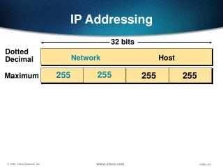
00001100 00100010 10011110 00000101 IP Addresses (IPv4) • Unique 32-bit number associated with an interface • on a host, on a router, …connect to ports, links, etc. • Association can be long-term or short-term • Use dotted-quad notation, e.g., 12.34.158.5: 12 34 158 5
01010000 01000100 00010011 01110011 11110000 10110111 00110011 00000111 Examples • What address is this? • How would you represent 68.115.183.7? 80.19.240.51
Routers in the Network • Routers connect links and networks together • Must forward packets towards destination ... ... host host host host host host LAN 2 LAN 1 router router router WAN WAN Router
Routers Send Packets to Correct Port Location of packet queues depends on switch design Node incoming links outgoing links Memory
1.2.3.4 1.2.3.5 Forwarding Table Plays Crucial Role • Table maps IP addresses into output interfaces • Forwards packets based on destination address 1.2.3.5 1 1.2.3.6 3 1.2.3.4 2 … … 1 2
forwarding table Scalability Challenge • Suppose hosts have random addresses • Then routers would need a separate entry for each host • Far too much state to hold in each router (why is it too much state?) 1.2.3.4 5.6.7.8 2.4.6.8 1.2.3.5 5.6.7.9 2.4.6.9 ... ... host host host host host host LAN 2 LAN 1 router router router WAN WAN 1.2.3.4 1.2.3.5
Two Universal Tricks in CS • When you need more flexibility, you add… • A layer of indirection • When you need more scalability, you impose… • A hierarchical structure
Hierarchical Addressing in U.S. Mail • Addressing in the U.S. mail • Zip code: 94704 • Street: Center Street • Building on street: 1947 • Location in building: Suite 600 • Name of occupant: Scott Shenker • Forwarding the U.S. mail • Deliver letter to the post office in the zip code • Assign letter to mailman covering the street • Drop letter into mailbox for the building/room • Give letter to the appropriate person ???
Who Knows What? • Does anyone in the US Mail system know where every house is? • Separate routing tables at each level of hierarchy • Each of manageable scale
Hierarchical Structure • The Internet is an “inter-network” • Used to connect networks together, not hosts • Forms a natural two-level hierarchy: • WAN delivers to the right LAN (i.e., deliver to zip code) • LAN delivers to the right host (i.e., deliver to house) ... ... host host host host host host LAN 2 LAN 1 router router router WAN WAN LAN = Local Area Network WAN = Wide Area Network
00001100 00100010 10011110 00000101 Hierarchical Addressing • Prefix is network address: suffix is host address • 12.34.158.0/23 is a 23-bit prefix with 29 addresses • Terminology: “Slash 23” 12 34 158 5 Network (23 bits) Host (9 bits)
11111111 00001100 00100010 11111111 10011110 11111110 00000101 00000000 IP Address and a 23-bit Subnet Mask Address 12 34 158 5 255 255 254 0 Mask
Scalability Improved • Number nearby hosts with same prefix • 1.2.3.0/24 on the left LAN • 5.6.7.0/24 on the right LAN 1.2.3.4 1.2.3.7 1.2.3.156 5.6.7.8 5.6.7.9 5.6.7.212 ... ... host host host host host host LAN 2 LAN 1 router router router WAN WAN 1.2.3.0/24 5.6.7.0/24 forwarding table
Easy to Add New Hosts • No need to update the routers • E.g., adding a new host 5.6.7.213 on the right • Doesn’t require adding a new forwarding entry 1.2.3.4 1.2.3.7 1.2.3.156 5.6.7.8 5.6.7.9 5.6.7.212 ... ... host host host host host host LAN 2 LAN 1 router router router host WAN WAN 5.6.7.213 1.2.3.0/24 5.6.7.0/24 forwarding table
“Subnet” Terminology • Think of LANs as special case of “subnets” • Subnet is region without routers containing addresses within the “subnet mask” • Could be a link, or LAN • Textbook has an operational definition of subnet • Remove all interfaces from hosts, switches • The regions that remain connected are subnets
History of Internet Addressing • Always dotted-quad notation • Always network/host address split (subnets) • But nature of that split has changed over time
Original Internet Addresses • First eight bits: network address (/8) • Last 24 bits: host address Assumed 256 networks were more than enough!
Nice Features • Transit routers looked at what portion of address? • Network • That portion of address space was flat • No need for hierarchy with 256 entries • Rest of address only relevant on host’s network • But did not provide for enough networks • Ubiquity of ethernet not foreseen
0******* 10****** 110***** ******** ******** ******** ******** ******** ******** ******** ******** ******** Next Design: Classful Addressing • Class A: if first byte in [0..127] assume /8 (top bit = 0) • Very large blocks (e.g., MIT has 18.0.0.0/8) • Class B: first byte in [128..191] assume /16 (top bits = 10) • Large blocks (e.g,. UCB has 128.32.0.0/16) • Class C: [192..223] assume /24 (top bits = 110) • Small blocks (e.g., ICIR has 192.150.187.0/24) • (My house used to have a /25)
1110**** 11110*** ******** ******** ******** ******** ******** ******** Classful Addressing (cont’d) • Class D: [224..239] (top bits 1110) • Multicast groups • Class E: [240..255] (top bits 11110) • Reserved for future use • What problems can classful addressing lead to? • Only comes in 3 sizes • Routers can end up knowing about manyclass C’s (/24s) • Wasted address space
Today’s Addressing: CIDR • CIDR = Classless Interdomain Routing • Flexible division between network and host addresses • Must specify both address and mask • Clarifies where boundary between addresses lies • Classful addressing communicate this with first few bits • CIDR requires explicit mask
00001100 00000100 00000000 00000000 11111111 11111110 00000000 00000000 CIDR Addressing Use two 32-bit numbers to represent a network. Network number = IP address + Mask IP Address : 12.4.0.0 IP Mask: 255.254.0.0 Address Mask Network Prefix for hosts Written as 12.4.0.0/15 or 12.4/15
CIDR: Hierarchal Address Allocation • Prefixes are key to Internet scalability • Addresses allocated in contiguous chunks (prefixes) • Routing protocols and packet forwarding based on prefixes • Recursively break down chunks as get closer to host : : : 12.0.0.0/15 12.3.0.0/22 12.2.0.0/16 12.3.4.0/24 : : 12.3.0.0/16 12.3.254.0/23 : : 12.0.0.0/8 12.253.0.0/19 12.253.32.0/19 12.253.64.0/19 12.253.0.0/16 12.253.64.108/30 : 12.253.96.0/18 12.253.128.0/17
Scalability: Address Aggregation Provider is given 201.10.0.0/21 (201.10.0.x .. 201.10.7.x) Provider 201.10.0.0/22 201.10.4.0/24 201.10.5.0/24 201.10.6.0/23 Routers in the rest of the Internet just need to know how to reach 201.10.0.0/21. The provider can direct the IP packets to the appropriate customer.