Spacecraft Attitude Determination Using GPS Signals
290 likes | 456 Vues
This paper presents a comprehensive analysis of attitude determination for spacecraft using GPS signals, specifically focusing on the C1C frequency. By employing dual receiver arrangements to measure phase differences from the same GPS satellite, we develop an integer resolution algorithm that enhances accuracy while minimizing loss functions. The study reviews previous work and outlines goals, methodologies, and results that demonstrate the effectiveness of the proposed methods for spacecraft orientation determination. We also discuss recommendations for improving techniques and avoiding common pitfalls.

Spacecraft Attitude Determination Using GPS Signals
E N D
Presentation Transcript
Spacecraft Attitude Determination Using GPS Signals C1C Andrea Johnson United States Air Force Academy
Outline • Concept review/ Prior work • Goals • Receiver arrangement • Integer resolution • Assumptions/ Coordinate Frames • Minimizing the loss function • Results • Conclusions • Recommendations
Concept Review • Two receivers detect the same GPS satellite signal • Phase differences can be used to determine the angle of the line defined by the 2 receivers
Concept Review Cont. • Determine matrix, A, that transforms baseline vector from body frame to LO • Issues • Find n • Accurate loss function minimization
Prior Work • Minimizing the loss function • Linear least squares • ALLEGRO (Attitude-Lean-Loping-Estimator using GPS Recursive Operations)
Prior Work Cont. • Linear least squares with motion-based integer resolution: • Non-linear, predictive filter assuming n has already been resolved:
Project Goals • Integer resolution algorithm • Non-IC dependent minimization technique incorporating integer phase difference measurements • Design computer code to perform attitude determination
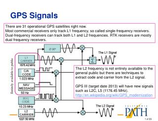
Master antenna Slave antenna Intermediate antenna Receiver Arrangement 12.50.5λ • 2 master antennas, 2 slaves, 4 intermediate • Non-military frequency: 1575.42 MHz, λ = 0.1903 m 12.50.5λ 5λ
2λ 3λ Φ1 Φ3 Φ2 Integer Resolution • Intermediate receivers • Variation of integer search • Unique solution to 2 phase difference measurements if baselines not multiples of each other • Third provides check • Accurate even for large baselines
zlo xlo ylo Assumptions/ Coordinate Frames • Algorithm uses single set of 3 receivers • Same 2 GPS satellites always in view • No masking or multipathing • “Inertial” reference frame: local orbital • Body frame = LO when roll, pitch, and yaw = 0
Minimizing the Loss Function • Linear • Diverges for poor initial guesses • Motion-based integer resolution • ALLEGRO • Does not account for n in algorithm • Separate motion-based integer resolution • Gauss-Newton • Not sensitive to initial conditions • Always converges • Designed for minimization of squared functions
Minimizing the Loss Function Cont. • Generating Test Data • 3 orbit propagators • 1 for spacecraft, 2 for GPS satellites • 2-body EOM, no perturbations • Ode5/Dormand-Prince numerical integration • Fixed time-step: 1 sec • 1 hour simulation
Minimizing the Loss Function, Cont. • 1 attitude propagator • Euler moment, no disturbance torques • Initialization program generates actual fractional phase differences and quaternions • Noise added with
Minimizing the Loss Function, Cont. • Gauss-Newton/ Gauss-Newton-Levenberg-Marquardt • Receiver locations written in body frame coordinates, units of wavelengths
Minimizing the Loss Function, Cont. • Unknown value is the A-matrix, must be converted to a vector for GN/GNLM
Minimizing the Loss Function, Cont. • Minimization equation requires solving for state using Gaussian elimination or decomposition • This is GN method
Minimizing the Loss Function, Cont. • Sometimes a singularity occurs: • To counter this, an additional term is needed: • If the singularity still occurs, multiply λ by 10 and recalculate
Minimizing the Loss Function, Cont. • Defining variables:
Minimizing the Loss Function, Cont. • Jacobian matrix:
Minimizing the Loss Function, Cont. • Determining attitude from the transformation matrix:
Minimizing the Loss Function Cont. Orbit Propagators (3) GPS 1, GPS 2, & S/C IJK vectors Initialization Program Attitude Propagator S/C actual quaternion 3 noisy Phase measurements Transformation matrix/ quaternions GN/ GNLM Program Integer Resolution Program 3 integer phase differences
Conclusions • Significant errors caused by several factors • GN/GNLM intended for vectors of parameters, not vectorized matrix • Use of constant to prevent singularities • Linear receiver arrangement • Only 2 sightlines used (minimum of 4 available) • GN/GNLM sensitive to measurement errors
Conclusions, Cont. • ALLEGRO remains most accurate • GN/GNLM with modifications may or may not perform better
Recommendations • Use matrix for singularity avoidance • Determine better method for comparing results of matrix calculations (compare entire matrix, elements thereof, or a combination of both) • Integrate integer resolution algorithm into GN/GNLM algorithm • If cannot use GN/GNLM, incorporate integer resolution algorithm into ALLEGRO algorithm