Download
1 / 29
471 likes | 1.06k Vues
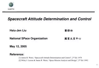
Spacecraft Attitude Determination and Control. Hsiu-Jen Liu 劉修任 National SPace Organization 國家太空中心 May 12, 2005 Reference: [1] James R. Wertz, “Spacecraft Attitude Determination and Control”, 2 nd Ed. 1978

E N D
Spacecraft Attitude Determination and Control Hsiu-Jen Liu 劉修任 National SPace Organization 國家太空中心 May 12, 2005 Reference: [1] James R. Wertz, “Spacecraft Attitude Determination and Control”, 2nd Ed. 1978 [2] Wiley J. Larson & James R. Wertz, “Space Mission Analysis and Design”, 2nd Ed. 1992
Course Outline • Attitude Determination and Control Subsystem (ADCS) Function • Impact of Mission Requirements and Other Subsystems on ADCS • ADCS Design Process • Define ADCS Control Modes • Define ADCS Requirements by Control Modes • Select ADCS Control Methods and their Capabilities • Attitude Control Type • Environmental Disturbance Analysis • ADCS Sensor Type • ADCS Actuator Type • Spacecraft Coordinate Systems • Spacecraft Dynamic & Kinematical Equations • FORMOSAT-3 Design Example
ADCS Function • The ADCS stabilizes the spacecraft and orients it in desired directions during the mission despite the external disturbance torques acting on it: • To stabilize spacecraft after launcher separation • To point solar array to the Sun • To point payload (camera, antenna, and scientific instrument etc.) to desired direction • To perform spacecraft attitude maneuver for orbit maneuver and payloads operation • This requires that the spacecraft determine its attitude, using sensors, and control it, using actuators
Impact of Mission Requirements and Other Subsystems on ADCS Mission Power Thermal Special thermal maneuvers required ? 1. Earth-Pointing or inertial-Pointing ? 2. Control during DV burn ? 3. Separate payload platform ? 4. Accuracy/Stability needs ? 5. Slewing requirement ? 6. Orbit ? 7. Autonomy ? 8. Mission life ? 9. On-board navigation data required ? 1. ADCS load 2. Special regulation Command & Data Handling Power Data processing capability 1. Solar array pointing requirement ? Propulsion 1. Thruster size 2. Propellant load Structures 1. Spinner vs. Active vs. Passive 2. Attitude determination (On-orbit or Ground) 3. Sensor selection 4. Actuator selection 5. Computational architecture 1. Center of mass constraints 2. Inertia constraints 3. Flexibility constraints 4. Thruster location 5. Sensor mounting Communications Antenna pointing accuracy ? ADCS Trades
ADCS Design Process (Cont.) - Attitude Control Type • Passive Control Techniques: • Gravity-gradient control uses the inertial properties of a spacecraft to keep it pointed toward the Earth. This relies on the fact that an elongated object in the gravity field tends to align its longitudinal axis through the Earth’s center. • Passive magnetic control uses permanent magnets on board the spacecraft to force alignment along the Earth’s magnetic field. This is most effective in near-equatorial orbits where the field orientation stays almost constant. • Spin stabilization is a passive control technique in which the entire spacecraft rotates so that its angular momentum vector remains approximately fixed in inertial space. Spin-stabilized spacecraft employ the gyroscopic stability to passively resist disturbance torques about two axes. • Three-axis Active Control Technique: • Spacecraft stabilized in three axes are more common today than those using passive control. • It can be stable and accurate but also more expensive, complex, and potentially less reliable. • Broadly, these system take two forms: one uses momentum bias by placing a momentum wheel along the pitch axis; the other is called zero momentum with a reaction wheel on each axis. Either option usually need thrusters or magnetic torquers for wheel momentum unloading.
ADCS Design Process (Cont.) - ADCS Control Methods and their Capabilities
ADCS Design Process (Cont.) • Control Example: Active Attitude Control System 太空環境 (Environment) Implemented by Software ADCS Hardware Disturbance 1.命令:衛星姿態 2.命令:衛星角速度 3.命令:衛星角加速度 控制器 (Controller) 致動器 (Actuators) 衛星動態 & 衛星軌道 濾波器 (Compensator) 1. 衛星姿態 (Quaternion) 2. 衛星角速度 (Angular Velocity) 估測器 (Estimator) 感測器 (Sensors) 1. 迴授訊號:衛星姿態 2. 迴授訊號:衛星角速度 General Structure of a Satellite Attitude Determination and Control Subsystem
ADCS Design Process (Cont.) • Typical Environmental Disturbance • Gravity-Gradient Torque: • Any nonsymmetrical object of finite dimensions in orbit is subject to a gravitational torque because of the variation in the Earth’s gravitational force over the object • Solar Radiation Torque: • Radiation incident on a spacecraft’s surface produces a force which results in a torque about the spacecraft’s center of mass • Aerodynamic Torque • The interaction of the upper atmosphere with a spacecraft’s surface produces a torque about the center of mass • Magnetic Disturbance Torque • Magnetic disturbance torques result from the interaction between the spacecraft’s residual magnetic field and the geomagnetic field
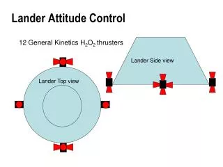
ADCS Design Process (Cont.) • Typical ADCS Actuators * Multiply by moment arm (typical 1 or 2 m) to get torque
Spacecraft Coordinate Systems Spacecraft body Coordinates Earth-Centered Earth-Fixed (ECEF) Coordinates Earth Centered Inertial (ECI) Coordinates Local Vertical Local Horizontal (LVLH) Coordinates
X X’ Spacecraft Attitude Definition • Spacecraft Attitude: the orientation of the body coordinate w.r.t. the ECI (or LVLH) coordinate system • Euler angle representation: • [ ] : rotate angle around X-axis, then rotate angle around Y-axis, then rotate angle around Z-axis • The transition matrix: • Quaternion: rotation an angle () around arbitrary axis (N) of ECI coordinate system: • Q = [ n1*sin( /2) n2*sin( /2) n3*sin( /2) cos( /2) ] • N [ n1 n2 n3 ]
Spacecraft Dynamic & Kinematical Equations • Dynamic Equation (3x1) to be stabilized: • I: Spacecraft moment of inertia • N: External torque (Thruster & Environment) • Hw: Wheel angular momentum • w: Spacecraft angular velocity • Kinematical Equation (4x1): • Q: Spacecraft quaternion
FORMOSAT-3 Design Example- Mission Requirements FORMOSAT-3 program has a goal to launch a constellation of six micro-satellites to collect atmospheric remote sensing data for monitoring weather and conducting climate, ionosphere, and gravity research.
Reaction Wheel Thruster#1 & #2 CSS#6 CSS#5 X-axis Magnetic Torquer Rod CSS#2 CSS#1 Z-axis Magnetic Torquer Rod CSS#3 Y-axis Magnetic Air-Core Torquer CSS#4 Thruster#4 CSS#8 CSS#7 Thruster#3 FORMOSAT-3 Design Example- ADCS Component Locations Legend: Location change
FORMOSAT-3 Design Example- ADCS Sensors & Actuators Sensors Actuators Earth Horizon Sensor Solid Core Torque Rod Magnetometer Air Core Torquer Coarse Sun Sensor Reaction Wheel
FORMOSAT-3 Design Example- Control Modes & Requirements Definition
Initially injected into parking orbit • Flight computer is rebooted The argument of latitude of the north of the orbit within the expected value Body rate < the expected value The error angle between +Z body axis and the Earth’s magnetic field vector is less than the expected value Launch Mode Separation and deployment observed from EPS ARS has diverged or no GPS Safehold Mode Spacecraft is tumbling ARS has converged and Nadir pointing > the expected value ARS has diverged or no GPS Nadir Mode Stabilize Mode ARS has converged and Nadir pointing < the expected value Spacecraft is tumbling Nadir pointing < the expected value Nadir pointing > the expected value Spacecraft is tumbling Nadir-Yaw Mode Command from Ground Thrust Completed ARS has diverged or no GPS Spacecraft is tumbling Thrust Mode FORMOSAT-3 Design Example- Control Modes & Requirements Definition Flow Chart
FORMOSAT-3 Earth Magnetic Field Orbit Plane FORMOSAT-3 Design Example- Spacecraft Orientation in Stabilize/Safehold Mode
FORMOSAT-3 Design Example- Spacecraft Orientation in Nadir/Nadir-Yaw Mode ROCSAT-3 Orbit Plane
FORMOSAT-3 Design Example- Modes Controller and Component Utilization
FORMOSAT-3 Design Example - Stabilize/Safehold Mode Simulation Attitude Rate • Initial Conditions: • 10° attitude bias for each axis • 2°/s attitude rate for each axis Magnetic Dipole Angle between body +Z and Earth Magnetic Field
FORMOSAT-3 Design Example - Nadir-Yaw Mode Simulation Attitude Rate • Initial Conditions: • 10° attitude bias for each axis • 2°/s attitude rate for each axis Attitude Bias Wheel Momentum
FORMOSAT-3 Design Example - Nadir-Yaw Mode Simulation (Cont.) Magnetic Dipole Angle between body +Z and Nadir
Exercise • Define the mission requirements of your satellite. • According to the mission requirements, define ADCS control modes and corresponding ADCS requirements. • Select the proper control type for each control modes.