Download
1 / 21
260 likes | 442 Vues
Attitude Determination and Control System. BY: CHANDRIKA BHARDWAJ. SATELLITE’S ATTITUDE. Orientation of satellite as perceived in a certain frame of Reference. CHANGE IN ATTITUDE. Satellite tends to change its orientation because of environmental torques Drag of residual atmosphere

E N D
Attitude Determination and Control System BY: CHANDRIKA BHARDWAJ
SATELLITE’S ATTITUDE • Orientation of satellite as perceived in a certain frame of Reference
CHANGE IN ATTITUDE • Satellite tends to change its orientation because of environmental torques • Drag of residual atmosphere • Solar radiation pressure • Gravity gradient • Interaction of Satellite electronics with earth’s magnetic field
ATTITUDE CONTROL • Needed because- • Payload requirements • Eg. Focusing the satellite camera to a particular location on earth • Communication requirements • Pointing the antenna towards ground • Power system requirements • Tracking the sun to achieve maximum power generation
Components of ADCS • Sensors- To determine the orientation and position of the satellite • Algorithms-To calculate the deviation from the desired orientation and to generate actuation command to counter the deviation • Actuators-To act upon the signals given by the control algorithms and to produce the necessary torqes
SENSORS • Measure the attitude of the satellite Types: • Gyroscopes: • Sense rotation in 3-D space without reliance on observation of external objects • Consists of a spinning mass, also includes laser gyros utilizing coherent light reflected around a closed path • Gyros require initialization by some other means as they can only measure “changes” in orientation
SENSORS contd… • All gyro instruments are subject to drift and can maintain orientation for limited times only (typically tens of hours or less) • Horizonindicators • Optical instrument that detects light at the horizon • Can be a scanning or staring instrument • Infrared is often used which can function even on the dark side of earth • Tends to be less precise than sensors based on stellar observation
SENSORS contd… • Orbitalgyro compassing • Uses a horizon sensor to sense the direction of earth’s centre • Uses a gyro to sense rotation about an axis normal to orbital plane • Hence it provides pitch and roll measurements • Sun Sensor • Senses the direction of Sun • Can be simple as solar cells and shades or complex as a steerable telescope
SENSORS contd… • Star Trackers • Optical device measuring the direction to one or more stars (using a photocell or solid state camera to observe the star) • Require high sensitivity ,may become confused by sunlight reflected from the exhaust gases emitted by thrusters • Global Positioning System(GPS) • Required for position measurements • Determines position and speed of the satellite in space
CONTROL ALGORITHMS Control Algorithms are computer programs that receive input data from vehicle sensors and derive the appropriate torque commands to the actuators to rotate the vehicle to the desired attitude
Details of Control Algorithms • “actuator andsensorprocessing” • Establishes the interfaces to the sensors and the actuators needed for attitude control • Determines the necessary commanding for the actuators from the torques computed by the layer estimation prediction control • Performs the time critical communications with actuators and determinates the state of actuators
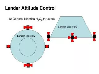
ACTUATORS • Apply the torques needed to re-orient the vehicle to the desired attitude Types: • Thrusters (often mono propellant rockets) • limitation:fuel • Spin -stabilization • Momentum wheels • Electric motor driven rotors made to spin in the direction opposite to that required to re-orient the vehicle
ACTUATORS • Make up a small fraction of the spacecraft’s body, are computer controlled to give precise control • Momentum wheels are generally suspended on ‘magnetic bearings’ to avoid bearing friction and breakdown problem • To maintain orientation in 3D space , minimum of 2 must be used ,additional units provide single failure protection
ACTUATORS • Control Moment Gyros • Include rotors spun at constant speed mounted on Gimbals • Provides control about the two axes orthogonal to the gyro spin axes, triaxial control still requires 2 units • CMG is a bit more expensive in cost and mass since , gimbals and their drive motors must be provided • Max. torque exerted by CMG is greater than than for a momentum wheel (suitable for larger spacecraft)
ACTUATORS • Drawback: additional complexity increases failure points • Solar Sails • Produce thrust as a reaction force induced by reflecting incident light • Used to make small attitude control and velocity adjustments • Saves larger amounts of fuel by producing control moments
ACTUATORS • Pure passive Attitude Control • Gravity gradient Stabilization • Magnetic Field Main advantage is that no power or fuel is required to achieve attitude control
REFERENCE SYSTEM • The three critical flight dynamics parameters are rotations in three dimensions around the vehicle’s coordinate system origin ,the centre of mass. These angles are pitch, roll and yaw. • Pitch: rotation around the lateral or transverse axis. Ex. Nose pitches up and the tail down or vice versa. • Roll: rotation around longitudinal axis. • Yaw: rotation about the vertical axis.
REFERENCE SYSTEM PITCH , YAW AND ROLL AXES
ADCS of PRATHAM • Sensors finalised : • SunSensors • Magnetometer • GPS • Gyros • Control Law • Actuator finalised: • Magnetorquer (as on 18 sept 2008)
REFERENCES • wikipedia,the encyclopedia • AAU CUBESAT • SISTEC • www.gpsdaily.com • ncube-norwegian satellite • Spot 4 • Pratham, ADCS documentation