Lunar Reconnaissance Orbiter Attitude Control System Overview
110 likes | 177 Vues
Understand the key requirements and specifications of the LRO ACS Subsystem for maintaining proper spacecraft attitude and pointing throughout the mission. Explore control modes and hardware implementation.

Lunar Reconnaissance Orbiter Attitude Control System Overview
E N D
Presentation Transcript
Attitude Control System (ACS) Eric Holmes, Code 591 Joe Garrick, Code 595 Jim Simpson, Code 596 NASA/GSFC August 16-17, 2005
Lunar Reconnaissance Orbiter (LRO)ACS SubsystemDocument Tree • Level 2 • 431-RQMT-000004 LRO Mission Requirements Document • 431-PLAN-000131 Lunar Reconnaissance Orbiter Spacecraft Performance Assurance Implementation Plan • 431-OPS-000042 Lunar Reconnaissance Orbiter Concept and Operations Document • 431-SPEC-000012 LRO Mechanical Systems Specification • 431-SPEC-000091 Lunar Reconnaissance Orbiter General Thermal Subsystem Specification • 431-ICD-000018 LRO Power Subsystem Electronics Electrical Interface Control Document • Level 3 • 431-SPEC-000162 Lunar Reconnaissance Orbiter Guidance, Navigation and Control Attitude Control System Specifications • 431-SPEC-000063 Flight Dynamics Specification • 431-RQMT-000113 LRO Pointing and Alignment Specifciation • 431-PROP-000017 LRO Propulsion Subsystem SOW and Specification • 431-ICD-000008 Lunar Reconnaissance Orbiter Electrical Systems Interface Control Document • 431-RQMT-000045 Lunar Reconnaissance Orbiter Radiation Requirements • 431-RQMT-000092 Lunar Reconnaissance Orbiter Thermal Math Model Requirements
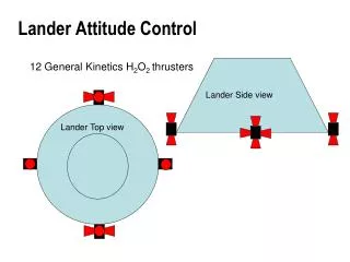
Lunar Reconnaissance Orbiter (LRO)ACS SubsystemLevel 2 Flow Down KeyRequirements Level 2 Req. Level 3: Requirements Concept/Compliance Paragraph Requirement MRD-084 LRO ACS will be responsible for maintaining the proper spacecraft attitude throughout the mission lifetime ACS needs to ensure proper pointing throughout lifetime MRD-088 MRD-089 MRD-091 ACS-3.2.4.1 ACS-3.2.5.1 ACS-3.2.6.1 ACS-3.2.7.1 The LRO ACS will implement the necessary control modes to meet all pointing requirements during all phases of the mission. - Sun Acquisition: coarse sun pointing for anomalous conditions - Observing: science taking mode - Delta-H: momentum unloading - Delta-V: orbit insertion, orbit adjusts and station keeping maneuvers. Control modes reflect pointing and functional requirements for the different phases of the mission MRD-084 MRD-085 MRD-087 ACS-3.2.12.1 ACS-3.2.13.7 ACS-3.2.14.2 ACS-3.2.15.1 ACS-3.2.16.1 The LRO ACS will utilize the hardware needed to implement the general and derived requirements stated in this ACS Specifications document. - IRU shall provide 3-axis angular rate and delta angle information to the ACS. - 8 CSS total to allow for as much spherical coverage as possible and for redundancy. - 2 STs to ensure the ACS onboard knowledge is maintained during occultations. - 4 reaction wheels for momentum storage and attitude control. - 8, 5 lbf (TBD) for attitude/orbit/momentum unloading - 2, 20 lbf (TBD) for orbit insertion/maintenance - Engine Valve Driver (EVD) electronics for thruster control - The ACS will interface with other spacecraft hardware electronics This list reflects the ACS hardware complement needed to meet requirements and with selective redundancy ensure minimal risk
Lunar Reconnaissance Orbiter (LRO)ACS SubsystemLevel 2 Flow Down KeyRequirements Level 2 Req. Level 3: Requirements Concept/Compliance Paragraph Requirement MRD-015 MRD-016 MRD-049 MRD-084 ACS-3.1.13.3 ACS-3.1.14.4 ACS-3.2.17.1 ACS-3.2.18.1 The LRO ACS will compute and provide HGA and Solar Array gimbal commands. -The ACS shall ensure commanding of the HGA to an accuracy of TBD degrees. -The ACS shall be responsible for commanding the Solar Array to an index position -The ACS shall ensure that the Solar Array tracks the sun to an accuracy of 5 degrees. ACS will determine and track pointing commands and slewing profiles for HGA and Solar Array Represents needed ACS and Mechanical allocations for pointing accuracies MRD-049 ACS-3.1.4.3 The LRO ACS shall meet the pointing, knowledge and stability requirements at the instrument interface associated with the Observing Mode. Knowledge (Resolution) ± 60.0 arcsec, per axis, (3s) Accuracy (Control) ± 30.0 arcsec, per axis, (3s) Stability 5 arcsec, per axis, over 1 msec. 10 arcsec, per axis, over 100 msec. 20 arcsec, per axis, over 4 sec. The LRO ACS shall meet the pointing, knowledge and stability requirements associated with all thruster modes. Knowledge (Resolution) ± 5.0 deg, per axis, (3s) Accuracy (Control) ± 0.1 deg, per axis, (3s) Stability N/A Accuracies needed to maintain velocity vector that will meet orbit maintenance requirements during burns ACS-3.1.5.2 MRD-049 MRD-087 MRD-092
Lunar Reconnaissance Orbiter (LRO)ACS SubsystemLevel 2 Flow Down KeyRequirements Level 2 Req. Level 3: Requirements Concept/Compliance Paragraph Requirement ACS-3.1.7.1 The LRO ACS shall meet the pointing, knowledge and stability requirements associated with the Sun Acquisition Mode. Knowledge (Resolution) N/A Accuracy (Control) ± 15 deg from targeted sun line, RSS (3s) Stability N/A Requirement to keep spacecraft in a power positive and thermally protected pointing MRD-090 ACS-3.1.3.1 All ACS control modes shall meet stability margins in accordance with established GN&C design practices with a single set of gains for the entire range of inertias over the mission lifetime, from Beginning of Life (BOL) to End of Life (EOL). Control system design practices that have long been used by GN&C will be employed here MRD-017 Need to keep frequency of science interruptions to a manageable level ACS-3.1.10.4 The ACS shall implement hardware and software capable of managing momentum for periods of no less than 2 weeks over the life of the mission. MRD-052 Prolonged sun exposure can damage science instruments ACS-3.1.12.1 The ACS shall ensure sun avoidance of science instruments to within 30 degrees of nadir (+Z axis ), or shall ensure the sun passes through their boresights with a rate of no less than 0.1 deg/sec.
Lunar Reconnaissance Orbiter (LRO)ACS SubsystemLevel 2 Flow Down KeyRequirements Level 2 Req. Level 3: Requirements Concept/Compliance Paragraph Requirement ACS-3.1.15.6 ACS-3.1.15.7 The LRO ACS shall provide a 180° yaw maneuver during the Observing Mode and shall take no more than 20 minutes. Yaw maneuver to keep sun on warm side of spacecraft and minimize science interruption MRD-018 MRD-005 MRD-006 MRD-026 MRD-027 ACS-3.1.10.1 ACS-3.2.3.1 Nulling of tip-off rates and residual despin rates will be initiated autonomously after separation, using thrusters or wheels. Wheels shall be able to handle up to 2.0 deg/sec, per axis. Use method that will ensure capability to null residual rates to allow transition to initial pointing. The ACS subsystem shall provide an onboard means of failure detection and correction (FDC) for anomalous conditions. ACS-3.2.11.1 ACS will monitor status and react appropriately to anomalies
LRO GN&C Nominal Control Mode Flow Separation = Command-Only Transition Power On / Reset = Autonomous (Post Separation) Transition = Autonomous (Nominal) Transition Momentum Level? Note that autonomous transition paths can also be commanded, but command-only paths cannot occur autonomously Autonomous (Post Separation Sequence, Thrusters) Autonomous (Post Separation Sequence, wheels) All Modes (FDC Corrective Action) CSS Sun Acquire (with and w/o gyros) Thruster Modes Delta-H Observing Mode Command Only Transition Inertial Pointing No transitions between Thruster Modes Autonomous Transition Delta-V Nadir Pointing (Primary Mission) Any Observing Sub-Mode can be commanded to any other Observing Sub-Mode Offset Pointing
Lunar Reconnaissance Orbiter (LRO)ACS SubsystemPreliminary Verification Approach • Components • All sensors and actuators, are expected to have been previously qualified • Acceptance testing required of all components (mechanical, thermal, and electrical) • Subsystem • Subsystem verification at the spacecraft level will be performed using a combination of functional and performance tests augmented by analysis and simulation • Dynamic simulator to perform hardware in the loop testing
Lunar Reconnaissance Orbiter (LRO)ACS Summary • LRO ACS driving requirements are defined • Pointing performance and ACS functional requirements have been defined • Preliminary architecture has been identified which will satisfy driving requirements • ACS control modes have been defined which will satisfy driving requirements • Interfaces between the propulsion system and the following subsystems have been defined at Level 3 and are being developed at Level 4: • Mechanical • Thermal • C&DH • Propulsion • Electrical • Power • FSW • ACS subsystem ready to proceed PDR • Performance and Functional Requirements Understood • Sufficient to Size Actuators • Sufficient to Proceed with Hardware Procurements • Sufficient to Develop Controller Algorithms