RACKS AND CABLES
RACKS AND CABLES. Peter Kim SLAC LST Install Readiness Review May 5, 2004. BRIEF OVERVIEW. SPACE ISSUES Where Do All the Cables Go? Cable Routing inside the Sextants Cable Routing Around the Detector Cable Routing to Outside Shielding Wall

RACKS AND CABLES
E N D
Presentation Transcript
RACKS AND CABLES Peter Kim SLAC LST Install Readiness Review May 5, 2004
BRIEF OVERVIEW • SPACE ISSUES • Where Do All the Cables Go? Cable Routing inside the Sextants Cable Routing Around the Detector Cable Routing to Outside Shielding Wall • Where to Mount the New Racks? • RPC Infrastructure Remains • Top/Bottom Sextants installed in 2004, Side Sextants in 2005 • Cylindrical RPC & ENDCAP RPC Operational after 2005 • Must Not Disturb BABAR Detector Components • SCHEDULE ISSUES Can We Meet 2004 Schedule P.Kim
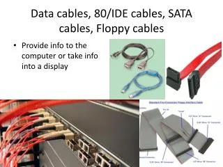
LST High Voltage System • HV Distribution (Baseline Design) • HV Supply located above Electronic Hut outside Shielding Wall (Racks No. 35, 36, 37) • One HV Cable (10-wire or 20-wire Kerpen) for each LST Module • Total of 564 Cables (94 Cables in each Sextant) • No Distribution Boxes near BABAR: Long Cables (25-35 m) “Warner Connectors”: Simplifies Cable Installation • Cable Trays & Cableways • HV Cables need to be Separated from Other Supply Lines • New Cable Tray under the Shielding Wall -> New Opening • New Cableways to run HV cable from Central BABAR Cable Ways to Middle of Each Sextant • Inside Each Sextant • Top/Bottom Sextants: Use Open Space Either Side of CENTER PLATE • Side Sextants: Use existing Black Box in the Middle P.Kim
HIGH VOLTAGE SUPPLY LST HV Supply Electronic Hut BABAR Detector RPC HV Supply P.Kim
HV CABLE ROUTING P.Kim
New Opening in the Shield Wall Radiation Safety O.K. 8 x 24 Cable Trays P.Kim
New Platform Near Shield Wall East Elevation Plan View P.Kim
New Platform • Design and Installation: M. Cramar • Design Near Complete; Submitted for Earthquake Safety Review Approval Expected Soon => Order Steel and Fixtures • Will Use Outside Vendor for Installation • Preassemble Platform and Make Mounting Hole Template before Aug. Shutdown • Install During Aug. 7 – 13 Drill Mounting Holes (20): ½ Day Mount Platform Using Crane: 2 Hours Install HV Trays, Ladder, and Support Structures: 2-3 Days Racks Install and Electric Conduits: 2-3 Days (parallel) P.Kim
Bottom Sextant P.Kim
. P.Kim
View of Side Sextant (2005) Side Plate Goes Back in Here P.Kim
Open Black Box Signal Readout Cable Box (2” Wide, 5” Deep) Signal Readout Cable Box (2” Wide, 5” Deep) Space Available for LST HV Cable (6” Wide, 5” Deep) GAS Tubes Goes Here P.Kim
HV System and NEC • New Cable Tray Design O.K. by SLAC Electrical Safety Committee (Perry Anthony) • Cable Tray Loading Capacity Specifications Signal Cables: 60% of the available cross sectional area Power Cables: 50% of the available cross sectional area (Power Cable = Voltage of 50 V and higher, OR amperage of 10 A or more) • We have 528 10-conductor Kerpen cables: 34320 mm**2 36 20-conductor Kerpen cables: 3420 mm**2 Tray Size = 24” x 7” (but only up to 6” can be used for this calculation) => 24” x 6” = 92903 mm**2 FILL RATE = 40.6 % Cable Trays In/Around BABAR Detector are Immune because BABAR is an APPLIANCE! P.Kim
High Voltage Cable KERPEN 6 kV HV Cable Zero Halogen, Frame Retardant Polymer Sheath Diameter: 9.1 mm for 10-conductors 10.7 mm for 20-conductors Minimum Bending Radius = 6 x Diameter Tinned copper, Flexible stranded Conductors (0.16 mm diameter) P.Kim
Status of HV Related Tasks • HV Distribution Box • Sun Workstations being removed for Distribution boxes, this week • First HV Distributions Crates under test at OSU • Cables to RPC HV supply and control lines, cable strain relief work still to be done. • HV Cables HV cables for 2 Sextants in 2004 delivered OSU/CSU making Cables including In-line Connectors • Cable Trays • Cable Trays has been ordered. Delivery on May 5. • Tray Install Outside Shield Wall will start soon. M. Cramar meeting Outside Vendor on May 5. P.Kim
LST Gas System • Gas Distribution • Reuse Rack space on Top of BABAR, currently occupied by RPC Crates. Enough empty slots for 2004 • New Gas Manifolds, but Reuse RPC Bubblers/Flow meters • LST Gas will be NON-FLAMMABLE • Re-Use RPC Teflon Tubes • Need to install 60 more lines (228 for RPC; 288 for LST) • RPC Tubes going to the Front Side need to be Rerouted (LST Gas Tubes go to Backward Side only) • Polyflo Tubes • Teflon/Polyflo Connections • Two Bundles of 24 Polyflo Tubes (Input & Output Lines) for each Sextant P.Kim
ReUse RPC Gas Tubes TEFLON Gas Supply Tubes TEFLON / POLYFLO Connections Backward Side Front Side TEFLON POLYFLO P.Kim
LST Electronics Readout • BASELINE DESIGN • Z-Strip Signal Read out from the Back Side 1152 Channels per Sextant • Phi Signal Read out from the Front Side 758 Channels per Sextant • AMPHENOL Twisted/Flat Readout Cable • Preamps on FEC, Not on the LST Module • 7 Crates for Z Signals and 6 Crates for Phi Signals • Output Digital Signal to DAQ via Optical Fibers • CRATE Features • VME Standard 6U High (26.5 cm); 19” Wide, 55 cm Deep • Allow 9U including Fan and extra 3U for air deflectors • Racks are all ordered and the last one shipped yesterday P.Kim
Racks at ESA 24U/36U Racks 11U Rack P.Kim
Amphenol Readout Cable MicroribbonTwitst/Flat Cable 17 Twisted Pairs Shielded & Jacketed Halogen Free Sheath Diameter at Round Section: 0.75 cm 96 Phi Cables / Sextant 72 Z Cables / Sextant Enough Room in Two 5 cm x 12 cm Cable Boxes / Sextant P.Kim
RACK LOCATIONS • Keep the Racks Close to LST Modules • Deterioration of Raw Signal over Distance • Higher Background Noise Pick Up over Distance • Space Considerations • Allow Access to Other Parts of BABAR Detector, Endcap Doors, Earthquake Braces, etc. • Cooling Fans / Air Circulation • Easy Removal and Install of FEC, Fans, Power Supply P.Kim
Electronic Rack Locations on the Forward Side 2004 2004 2005 2004 New Platform 2005 2004 HV Cable Tray P.Kim
Electronic Rack Locations on the Backward Side 2004 2004 2005 P.Kim
Top/Backward CratesOn a Movable Platform Side by Side Design for Height Clearance A. Constable All Parts Delivered/Fabricated. Ready for Assembly P.Kim
Artist’s Version of Cabling from Gigi/Angelo P.Kim
IFR DAQ Crates • Re-Use Existing 4 RPC DAQ Crates Replace Top/Bottom RPC Cards with LST IFB Cards Unused Extra Card Slots Available • Make Cable Connections BEFORE Doors Open • Use Existing Optical Cables (Control & Signal) from DAQ Crates to BABAR DAQ System • Control Cable Length Between FEC and DAQ Crates must be the same for ALL CHANNELS (19 m for RPC) MAKE CONTINGENCY TO CABLE LENGTHS SO WE CAN MOVE DAQ CRATES IN 2005 P.Kim
. P.Kim
. P.Kim
CRITICAL PATH DATES • AUG 3 • DAY Shift Only Time Available for Access before DOORS OPEN (3:30 PM) • ALL RPC Work in the Area Hidden by Doors must be completed • LST IFB Board Install in BDAQ Crates and Cabling MUST BE FINISHED • AUG 14 • Bottom Sextant LAYER-18 Module Installation • Shielding Wall disassembled on Aug. 7 • New Platform and HV Cable Tray Installed (Estimated time: 3 days) • Racks/Crates for Bottom Sextant installed and Checked out • HV Cables and Gas Lines for Layer-18 • AUG 23 • Rest of Bottom Sextant LST Module Installation Begins • All Utilities & Readout System For Bottom Sextant Ready P.Kim
MANPOWER • TRAY and New Platform Install Use Outside Vendor, Contact Person: M. Cramar • Cable/WireWays Install P Kim, H Rogers, C. Nix, S. Swain, S. Fan (Group E) + Gibson Locke • Electrical Install Sam and EFD Crew • Cabling and QC LST Module Install Shifters, INFN Electronics Group P.Kim
SUMMARY • Design Work for 2004 Install Mostly Complete • Parts for HV/Gas/Electronics Ordered and Being Delivered Daily • Preparing for Pre-Installation of Components that Can be done Before Aug. Shutdown • Working on Detailed Schedule During the 1st 10 Days with Jim K. • Working Toward the Goal of Complete QC TEST of Modules using FULL DAQ System during LST Installation P.Kim