Download
1 / 33
340 likes | 479 Vues
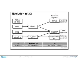
Agenda. Agenda. What is so different from GSM?. Number of different Radio Bearers Speech, video, streaming, up to 128/384 PS, up to 384/HS Combinations of different Radio Bearers Number of features in Radio Network Connection Handling and Channel Switching Handover and Power Control

E N D
What is so different from GSM? • Number of different Radio Bearers • Speech, video, streaming, up to 128/384 PS, up to 384/HS • Combinations of different Radio Bearers • Number of features in Radio Network • Connection Handling and Channel Switching • Handover and Power Control • Significant impact on RAN capacity • Number of features in Transport Network • Inverse Multiplexing over ATM • AAL2 Quality of Service separation • AAL2 switching and Transport Aggregation
WCDMA Network Topology CS Core MGW MSC/Call Server Iu CS Mur Iu ATM Switch Mut Mub Iub Iu PS RNC Iub Iur ATM Switch (RXI/MSN) WCDMA RAN RBS/NodeB Mub SGSN Uu PS Core RNC GGSN RBS/NodeB
UMTS Layered Architecture Agenda
General Features of a WCDMA RAN • Wide bandwidth • Chip Rate of 3.84 Mcps • Bandwidth of 5 MHz • The wide bandwidth reduces sensitivity to muti-path fading • Power Control • Common shared resource that makes WCDMA RAN flexible • Allocates power to each subscriber and ensures that each user and service creates the minimum of interference • One-cell Frequency Reuse • Supported by RAN through Orthogonal Variable Spreading Factor (OVSF) codes for channelization of different subscribers Agenda
General Features of a WCDMA RAN • Frequency Division Duplex • Used when UL and DL are on different frequencies • Macro Diversity • Used for transmission between Ue and RBS • Allows simultaneous use of links between the Ue and two or more RBS’s • Provides smooth transition as Ue moves: • Between cells of the same RBS (softer handover) • From one RBS to another (soft handover) Agenda
HSDPA High Speed Downlink Packet Access • Speed • More advanced audio & video content & larger file transfers • Reduced down load time • Peak data rates 8 -10 Mbps => Improved end-user experience • Less delay • Web browsing (WWW) • New services with very high requirements on response times, e.g. gaming applications => Improved end-user experience • Capacity => Reduces the cost per Mbyte for operators • HS-DSCH coverage as good as R99: => No need for new sites Agenda
UMTS Network TE MT WCDMA RAN CN Iu edge node CN Gateway TE End-to-End Service TE/MT Local Bearer Service UMTS Bearer Service External Bearer Service RAB CN Bearer Service Radio Access Bearer (RAB) Agenda
RAB Examples Conversational Speech 12.2 kbps Circuit switched Conversational CS Data 64 kbps Circuit switched Streaming 57.7 kbps Circuit switched Variable rate Packet switched Interactive Combination of Conversational Speech and Interactive 64/64 Multi-RAB Agenda
RXI 820 RNC 3810 RBS 3000 RBS 3000 or WCDMA RAN: End-to-end view end-to-end application traffic PDCP PDCP RLC RLC MAC MAC WCDMA PHY L1 WCDMA PHY L1 AAL2 AAL2 AAL2 AAL2 AAL2 AAL2 AAL2 AAL2 ATM ATM ATM ATM ATM ATM ATM ATM Transmission Transmission Transmission Transmission Transmission Transmission Transmission Transmission RNC Node B ATM Switch UE Agenda
Inter RAT Handover Using the WCDMA Frequency Using the GSM Frequency WCDMA Coverage GSM Coverage Road Inter Radio Access Technology (RAT) handover Agenda
Sample rollout timeline of 1RNC/200 RBS Standard 8wks delivery However can be quicker. This phase dependent on total RBS count and weekly run rate TCM can actually start to generate script as soon as ATND is done. Agenda
Access Transport Network Design • What is ATND? • RAN Topology Model • ATM Aggregation Strategy • Transport Network Topology towards Circuit and Packet Domain • Transport Network Topology between RNCs • Optimizing Node B Clusters Connectivity within the RNS • RNC Iub, and Iur Dimensioning • QoS Design - Coordination of ATM Service Category and Traffic Descriptors
WCDMA Access Transport Network Design • Why? • To effectively plan new networks and enable utilization of existing transport infrastructure for transportation of WCDMA services and applications • Future proof network planning and design (growth & expansion) • Design consideration to meet key operational and future optimization requirements • Design of ATM network characteristics to aim for optimum end-user perceived quality • Resilience and Recovery
WCDMA Access Network – Problem Statement • How can I achieve a balanced RAN Transport Design that meets my short, medium and long term goals? • What are my design considerations to ensure a future proof network planning & design? • How do I handle configuration of additional T1 capacity for user data? • Do I need to establish further redundancy in my network? • How do I know my Iub and Iur dimensioning can meet my forecast? • How many ATM PVCs should I have for user and signaling data?
ATM Aggregation Ericsson WCDMA TN Transmission 2G TN 3G Access Transport Network Design Payload on AAL2 WCDMA Application Channels ATM Adaptation Layer WCDMA RAN Transport ATM Layer Physical Layer Common Transmission
Nominal Cell Plan Topology Model Development No RBS, Cluster, PoC Capacity Calculation SDH Pre-Planning RNC Iub, Iur, Iu Dimensioning Topology & Capacity OK? Nominal Transport Plan Detailed Cell Plan Yes Physical Link Detailing Physical Circuit PVC Detailing Detailing Detailing RBS/RXI/RNC Detailing Link & Node Specification Detailed Transport Plan ATND Process Flowchart
Acceptance and Conclusion Information Gathering Start-Up ofProject Access Transport Network Planning Review and Finalize ATND Spec ProjectPlan Detailed Transport Network Design RAN Access Transport Network Design Process Requirement Specification SolutionSpecification Network Design Report High Level Design Specifications Detailed Design Specifications - Network Design activities -Network Design service deliverables
ATND Service Deliverables • Deliverables • Project Management • Knowledge transfer • ATND Network Topology • Requirements on external transport infrastructure • Logical Network Layout • Physical Port Layout • Control Layer signalling design • Basic IP Addressing Plan • UTRAN Network Modelling • Iub and Iur design • ATM/AAL2 QoS and traffic descriptors • Design of MTP3b Signaling POC for Iu/Iur interfaces • Final report containing detailed design specification document • Complete ATND Questionnaire for network roll-out • Design Input: • Overall E2E Architecture • Forecast of number of customers, Services and Deployment • Traffic profile • Existing Transport Network Infrastructure • IP Address Space • SS7 Signaling Point Codes • Possible / Preferred Location of New Equipment • Preferences on Network Design
ATND Experience & Lessons Learned • RAN Access Transport Design is a long, complex and iterative negotiating process involving • RF Design • Circuit Core Network Design (possibly from another vendor) • Packet Core Network Design (possibly from another vendor) • RAN-Core Transport Interconnect • Configuration Mgmt & • Network Rollout • Requires in-depth competence and experience not only with General ATM & Sonet, but also with the RAN Vendor implementations of ATM and Sonet • Design is only done on paper, translating this into implementation requires extensive coordination with multiple organizations • Requires a good understanding of short, medium & long term requirements while maintaining a healthy balance between all of them
Experience & Lessons Learned Cont. • RAN Access Transport Design should be coordinated together with Core Network Design • ATM PVCs, ATM VPI and VCI Addressing Schemes • IP Addressing • Signaling & User Plane dimensioning and design • Some key access transport design aspects that require special attention • Access Transport (ATM) Aggregation Strategy • Striking the right balance of the available capacity between • Voice • R99 Packet data • HSDPA • RBS distribution within the RNC • Capacity vs. Redundancy issues
Packet Core Network Design Service What is included • SGSN Questionnaire (CIQ) • SGSN Node properties • Iu-PS interface • Gn/Gp interface • Gom interface • Gr interface • Only 10 RNCs per SGSN due to Cingular Requirements Agenda
Core Network Design (CS) • High level Design and a Proposed Architecture Solution Topology • Identifies nodes, functions and capacity, including high-level routing policies, robustness and redundancy • High level inter-site traffic figures/Call flows • Signaling design and synchronization • Detailed Node Design (MSC Server & MGw) • Traffic profile used for design/dimensioning • MSC-S capacity (CPU and memory) • Link dimensioning (SS7 and SIGTRAN (GCP,BICC,MAP,RANAP)) • T1 mapping/PCM range allocation) • IU design / Port assignments • "Traffic to SIGTRAN route assignments in MGW and MSC-S
Core Network Design (PS) • High level Design and a Proposed Architecture Solution Topology • Packet Network Topology Model per region, including connectivity design, routing, robustness and redundancy • High level inter-site traffic figures/Call flows (Intra and Inter SGSN) • Signaling design and synchronization • Detailed Node Design • Traffic profile used for design/dimensioning • Planning connection to other PLMNs - Gp as applicable • Gn, Gi & Gom Planning • Iu OC-3 Link Dimensioning • IuPS Traffic Descriptors • RNC ID Numbering Scheme and IP Addressing Scheme • Support system (DNS/NTP) • SS7 dimensioning (Gr)
Core Design Service Deliverables • Design Input: • Overall E2E Architecture • Forecast of number of customers, Services and Deployment • Traffic profile • Existing Transport Network Infrastructure • IP Address Space • SS7 Signaling Point Codes • Possible / Preferred Location of New Equipment • Preferences on Network Design • Deliverables • Project Management • High level design and network architecture (planning phase) • Detailed network design including a final report containing detailed design specification document • Complete and ready design Questionnaire for network roll-out
RAN Architecture – Traffic and O&M O&MDesign RAN TND
OAM Network Design Agenda
O&M Network Design • Deliverables • Detailed IP addressing plan • Dimensioning for RAN Mut, Mub and Mur interfaces, COMINF services dimensioning • Citrix, Alex and netback up dimensioning • O&M network topology OSS RC/COMINF servers • Planning network connectivity through FW and O&M Router/s • O&M VLANs for O&M and backup traffic • Ethernet switch ports planning
UTRAN tools and analysis • Performance statistics (Radio and Transport, GPEH) • Analysis and "data mining" to identify performance improving actions • Call flows (UETR, TEMS, Protocol Analyzer) • Root cause analysis of unexpected behavior • Logs (Alarm, Event, Availability, NE error logs) • Analysis to identify network instability and possible software or configuration faults Need of End-to-End UMTS knowledge to understand how different parts of the system (UE, Radio Network, Transport Network, Core Network) affect the overall performance and user experience.
Lessons learned from similar projects • T1 quality has been a problem in RF tuning • Log file analysis to classify dropped calls • Initiated a process to collect statistics for T1 quality monitoring and open CTS tickets based on them • GPEH analysis to identify missing neighbors • Supported first round of RF tuning with two sets of GPEH analysis to identify missing neighbor definitions • Identified AAL2 setup problem in the Core Network • Access failure root cause was identified and isolated to CN • Detailed analysis and testing was performed in one market to provide a workaround to UMSCs across the markets
Lessons learned from similar projects • IRAT (UMTS to GSM handover) • UTRAN had the leading role in IRAT configuration and testing nationally • IRAT problem on I-5 North was isolated to Los Angeles GSM network and successfully resolved • Reason for current poor IRAT KPIs was identified and isolated to the Core/GSM Network • Uplink interference investigation • UTRAN has been supporting the ongoing uplink interference investigation with snapshot and average values of interference and transmitted code power


