Download
1 / 19
190 likes | 202 Vues
A discussion on different types of corrosion and wear (and their associated mechanisms) followed by an overview of commercially available mitigation techniques, including their practical downhole applications are the focal points of this paper. Visit: https://westernfalcon.com

E N D
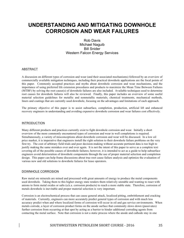
UNDERSTANDING AND MITIGATING DOWNHOLE CORROSION AND WEAR FAILURES Rob Davis Michael Naguib Bill Snider Western Falcon Energy Services ABSTRACT A discussion on different types of corrosion and wear (and their associated mechanisms) followed by an overview of commercially available mitigation techniques, including their practical downhole applications are the focal points of this paper. Commonly accepted practices and myths about downhole corrosion and wear mechanisms, and the importance of using preferred life extension procedures and products to maximize the Mean Time Between Failures (MTBF) by solving the root cause(s) of downhole failures are also included. Available techniques used to determine root causes for downhole failures will also be reviewed. Finally, this paper includes an overview of some useful material selection guidelines for metallic and nonmetallic materials, chemical treatments, mechanical methods, liners and coatings that are currently used downhole, focusing on the advantages and limitations of each approach. The primary objective of this paper is to assist subsurface, completion, production, artificial lift and enhanced recovery engineers in understanding and avoiding expensive downhole corrosion and wear failures cost effectively. INTRODUCTION Many different products and practices currently exist to fight downhole corrosion and wear. Initially a short overview of the more commonly encountered types of corrosion and wear in well completions is required. Simultaneously, a variety of misconceptions about downhole corrosion and wear will be discussed. In a low oil price market, it is imperative that engineers install the right solution to their downhole failure problems on the very first try. The cost of arbitrary field trials and poor decision-making without accurate pertinent data is too high to justify making the same mistakes over and over again. It is not the intent of this paper to serve as a complete text covering all of the possible causes of downhole failures; however, it is intended to act as a guide to help subsurface engineers avoid deterioration of downhole components through the use of proper material selection and completion design. This paper can help frame discussions about true root cause failure analysis and optimize the evaluation of various new and old solutions to downhole failures for lease operators. DOWNHOLE CORROSION Raw metal ore minerals are mined and processed with great amounts of energy to produce the metal components used downhole. Taking them to this higher energy state renders them relatively unstable and wanting to react with anions to form metal oxides or salts (a.k.a. corrosion products) to reach a more stable state. Therefore, corrosion of metals downhole is inevitable and proper material selection is very important. Corrosion is an electrochemical process that can cause general attack, localized pitting, embrittlement and cracking of materials. Currently, engineers can more accurately predict general types of corrosion and with much less accuracy predict when and where localized forms of corrosion will occur in oil and gas service environments. When metals corrode, a layer of corrosion product forms on the anode surface that commonly slows down (passivates) further corrosion from occurring at that spot by acting as a barrier to hinder additional corroding agents from contacting the metal surface. Note that corrosion is not a static process where the anode and cathode stay in one SOUTHWESTERNPETROLEUMSHORTCOURSE-2016 35
place; in fact, they commonly move and relocate over time. Below is an abridged list of common downhole corrosion types with a brief description of each: • CO2 Corrosion – Carbon dioxide dissolves in water lowering the pH and creating carbonic acid that reacts with the iron in steel to form iron carbonate. Depending on many different influential properties of the service environment, CO2 can cause both localized and general corrosion of downhole components. Elevated velocity (particularly in the presence of H2S also) can cause removal of the protective iron carbonate film accelerating CO2 corrosion downhole in a phenomena known as Flow Induced Localized Corrosion (FILC). It is common to see this type of localized attack on the OD of sucker rod couplings in Sucker Rod Pumped (SRP) wells producing large volumes of fluid where fluid velocities increase (at the couplings compared to the rod body). Because the cross-sectional area between the rod boxes and tubing ID is smaller, the local fluid velocity increases. Common practices used to prevent FILC on the sucker rod couplings are using tenacious filming amine corrosion inhibitors and/or Spray Metal (SM) sucker rod couplings, that are covered with a nickel based corrosion resistant metal. Velocity induced CO2 corrosion is also addressed in API RP 14E that suggests maximum velocities for steel tubulars in sweet gas wells. • H2S Corrosion – Hydrogen Sulfide is an aggressive water-soluble pitting agent that can also induce cracking in many alloys. General weight-loss corrosion from H2S is usually not a common concern in oil and gas production environments. Catastrophic failure from Sulfide Stress Cracking (SSC) and small deep localized pits (especially in high chloride environments) are the most common failures seen in downhole components exposed to sour fluids. Higher strength materials are more susceptible to SSC. Since hardness is a direct indicator of material strength, one of the most commonly accepted criteria for resistance of carbon and low alloy steels to SSC is to maintain hardness levels below Rockwell C Hardness (HRC) 22. • Chloride Corrosion – Chlorides can cause both pitting corrosion and cracking in downhole components. The iron chloride that forms from the reaction of steel in saline environments is unstable and readily dissolves causing an autocatalytic process that can be as much as 100 times faster than uniform corrosion. Crevice corrosion, a type of localized attack in confined spaces, is also common in environments with high chloride concentrations. • Oxygen Corrosion – Oxygen can act as both an oxidizer and cathodic depolarizer accelerating the reaction at both the anode and cathode of the corrosion cell causing rapid weight-loss corrosion. One example of this is when the packing of a stuffing box on a SRP well leaks during the down stroke introducing air into the top of the production string. Unaddressed, this simply repaired problem can cause very fast deterioration of the wellhead and top of the tubing string. Removing dissolved oxygen from injected water and using oxygen scavengers in packer fluids are common practices used to prevent oxygen corrosion downhole. • Microbiologically Influenced Corrosion (MIC) – Naturally occurring (in downhole reservoirs and on the surface) bacteria such as Sulfate-Reducing Bacteria (SRB) and Acid Producing Bacteria (APB) are sessile organisms that form biofilm colonies on the surface of downhole components (commonly in areas of lower velocity). The metabolism of SRB produces H2S by reducing sulfates and APB produce low molecular weight organic acids (such as acetic or formic acid), which collect under the biomass and form pits rapidly corroding steel and other alloys. Their round shape together with the presence of smaller round pits contained within larger round bottom pits often distinguish pits caused by MIC. This form of localized pitting is very difficult to predict and effectively treat. If the bactericide used to eradicate bacteria from the well fluid does not destroy the bacteria, they can become temporarily dormant by forming spores and then flourish again once the environment is conducive to their growth. • Galvanic Corrosion – Whenever two dissimilar metals are electrically coupled in an electrolyte, one will preferentially corrode to protect the other one generating a DC voltage. This reaction is used to protect tanks and pipelines by connecting sacrificial aluminum or magnesium anodes to the steel structure, in a process known as cathodic protection. The anode preferentially corrodes to protect the steel structure from corrosion. This same electrochemical process can be detrimental and cause premature accelerated failure. When a nickel (more noble metal on the galvanic series) plated packer is scratched during installation, exposing a larger surface area of nickel to a small surface area of the less noble carbon steel structure under the nickel plating, the steel is rapidly degraded at the scratch. The significant difference in anode and cathode surface areas in this example correlates to a large current density at the steel anode resulting in very high corrosion rates. In highly corrosive well environments, N-80 couplings also preferentially SOUTHWESTERNPETROLEUMSHORTCOURSE-2016 36
corrode when connected to J-55 tubing. This is thought to be caused by the less corrosion resistant quenched and tempered microstructure of N-80 steel compared to the as-rolled microstructure of J-55. COMMON MISCONCEPTION 1: Historically, classification of defects found during inspection of downhole tubulars is accurately divided into internal and external defects; however, the defects are often inaccurately classified as “pitting” or “wear” based on the shape of the defect. The electromagnetic and ultrasonic instruments used to inspect tubing and sucker rods are designed to look for defects with different geometric shapes. For example, an instrument designed to find sharply contrasting defects, like pits, commonly will not accurately detect gradual wall loss like uniform corrosion and vice versa. Most nondestructive inspection equipment employs multiple instruments and techniques to grade used tubing or sucker rods so defects of many commonly encountered shapes and sizes can be located. In fact, a defect classified as “pitting” could be a missing rolled-in slug in seamless tubing that occurred during its manufacturing process; and, a defect classified as “wear” may be general corrosion caused by a combination of low pH water and CO2. Caution should be taken when using tubular inspection data descriptions to determine what mechanism (wear, corrosion pitting, and/or other) caused the defect in tubing, to avoid inadvertently using sucker rod guides or spray metal sucker rod couplings to solve a general corrosion problem. It is important to note that the accuracy of electromagnetic and ultrasonic inspection of oil country tubulars is highly dependent on the equipment used, proficiency and attentiveness of the operator, proper calibration, and proper prove up of defects. In many cases, a combination of both electromagnetic nondestructive testing and API pressure testing is warranted before rerunning used tubulars downhole. COMMON MISCONCEPTION 2: While it is very common to successfully use J-55 tubing in shallow sour wells, no hardness testing and very limited metal chemistry controls (only sulfur and phosphorus) are required for tubing to meet J-55, N-80 and P-110 requirements. It is well known that API 5CT N-80 tubing is not acceptable for sour service but L-80 tubulars are. API specification 5CT requires hardness testing and controls six different chemical elements for tubing to meet L-80 requirements. It is not uncommon that an occasional joint of tubing that meets all necessary requirements for API J-55 fails from SSC in a sour SRP well. Further testing (beyond current API 5CT requirements) and more strictly controlled manufacturing practices would be required to minimize SSC failures in J- 55 tubing. COMMON MISCONCEPTION 3: It is commonly thought that produced waters with higher chloride concentrations are more corrosive to mild steel components used downhole. In fact, extremely saturated salt water (over 25% sodium chloride) in room temperature water exhibits a corrosion rate on steel of less than 0.4 mm/year (16 mils/year). The corrosion rate actually peaks around 1.8 mm/year (71 mils per year) at a concentration of approximately 3% sodium chloride. This data only considers sodium chloride alone dissolved in water at ambient temperature. Factors such as pH, velocity, temperature, and the presence of other chemicals (such as H2S) can drastically alter the measured corrosion rates in fluids containing different chloride levels. In fact, production environments containing chlorides together with both CO2 and H2S present one of the most difficult problems for proper downhole materials selection. DOWNHOLE WEAR The various types of corrosion encountered downhole are more commonly discussed, understood and accepted in the oil and gas industry. However, it is also common to discuss how “wear resistant” or “abrasion resistant” a product or material is (in absolute terms) and how it compares to other products/materials. It is also easy to find standardized wear test data that can substantiate both sides of contradictory claims that one material is more “wear resistant” than another. Before comparing materials and test data, it is very important to understand the types of wear experienced in the downhole situation under investigation and to choose a test that produces representative data for each proposed type of solution. Introduction of moving components downhole, like those in artificial lift systems, is commonly the cause of premature wear induced failures. COMMON MISCONCEPTION 4: Historically, abrasion test data comparing abrasive wheels under load on a polymer slab at room temperature in a dry environment (TABER® Abrasion) was used to represent how effectively a product may perform to stop rod on tubing wear downhole. Is this really representative? The properties of a polymer vary dramatically with varying temperature, pressure, and service environment compositions (aqueous, SOUTHWESTERNPETROLEUMSHORTCOURSE-2016 37
aqueous/oil/gas, etc.…). For example, a given side load at the top of the well (lower temperature) may be acceptable (below the modulus of a polymer rod guide or liner) but exceed the compressive strength and modulus of the same material just ten joints deeper in the same well. It is no longer acceptable for a product manufacturer to pick and choose wear test data that makes their product appear “wear resistant” while ignoring other types of wear tests that show the weaknesses of the product to abrasive conditions. It is also unacceptable to perform unrepresentative or misleading standardized tests just to generate comparative data on different products because it can result in misapplication of materials. In fact, if different materials fail by different mechanisms under the same operating conditions, then the use of a single test may lead to the wrong decisions when selecting the proper solutions for a wear problem. For example, a thin coating layer may provide improved resistance to abrasive wear but not have enough elasticity, thickness, adhesive strength, or impact resistance to maintain adhesion to the tubing or sucker rod it is applied on; thereby, failing by a different mechanism or combination of mechanisms in a short time period. A holistic understanding of material properties and review of all relevant test data is required to make difficult proper material selections in a downhole environment. Although wear is primarily a mechanical process, there are many different types of wear. In any system where wear occurs, the following are required: contacting materials, geometrical parameters (size, shape, roughness, etc.), relative motion, loading, environment, and lubrication. Below is a list of common types of wear with a brief description of each: • Abrasive Wear – Abrasive wear is defined as “wear in which hard asperities on one body penetrate the surface of a softer body and ‘dig’ material from the softer surface, leaving a depression or groove.” Examples of abrasive wear are gouging, grinding, scratching, and polishing. It can be limited to the two bodies in the definition that move relative to each other or it can include a third body or asperity such as sand in between a reciprocating sucker rod and stationary tubing ID. • Adhesive Wear - Adhesive wear occurs when multiple surfaces maintain frictional contact causing microscopic welding at the interface resulting in unwanted displacement and attachment of wear debris. Examples of adhesive wear are galling and scuffing which can commonly be prevented by using a lubricant. • Erosive Wear – Erosive wear is characterized by the direct impingement of solid particles, liquids or gas on a solid surface. The impacting particles commonly remove material from the solid surface by repeated deformation and cutting actions. Examples of erosive wear are blasting of a steel panel with an abrasive suspended under air pressure and erosive turbulent cavitation of previously dissolved CO2 bubbles breaking out of solution because of an abrupt change in diameter, velocity, and pressure at a crossover sub in a tapered production string. • Fretting Wear - Fretting wear is a process that occurs at the contact between two materials under cyclical load and subject to minute relative motion by some force, like vibration, that forms micropits by removing material from one or both surfaces of the materials. • Corrosive Wear – Corrosive wear is defined as the degradation of materials in which both corrosion and wear mechanisms are involved. The combined effects of wear and corrosion can result in material losses that are much greater than the additive effects of each process alone. The passive film (corrosion product) that typically hinders a corrosion reaction from proceeding is removed by wear in a cyclically repeating process causing rapid failures in some cases. One example of corrosive wear is the removal of corrosion products on a sucker rod coupling and/or tubing ID surface by a moving rod allowing the exposed fresh metal to rapidly react with corrosive produced fluids forming a new corrosion product film which is repetitively removed. Tubing failures as fast as a few weeks have been reported by this phenomenon. • Interfacial Wear – Interfacial wear is a degradation specific to plastic materials involving adhesive forces and an increase in temperature from frictional energy dissipation at the interface of a sliding polymer against a hard counterface. The thermal energy released from friction can change the properties of the plastic surface by softening, deforming or even melting the plastic. One example of this is rapid degradation of a sucker rod guide on the ID of downhole tubing at temperatures near or above the Vicat softening point (not recommended) of the sucker rod material. COMMON MISCONCEPTION 5: When a root cause failure analysis is conducted, it is common to focus on attempting to find one individual mechanism or culprit that caused the failure and address that single concern. Usually downhole failures are caused by multiple corrosion and/or wear processes working together. If a failure is SOUTHWESTERNPETROLEUMSHORTCOURSE-2016 38
caused by a combination of both rod on tubing wear and corrosion, then failures can happen in a very short time span (as in several weeks); whereas, if only wear or corrosion alone cause the failure it may take several years. The synergistic cyclical removal of the passive corrosion products by the moving rods followed by immediate corrosion of the tubing and rods by the production fluids yields a failure that looks like rod on tubing wear because it only occurs where the rods are wiping away the protective corrosion product. When these rapid failures occur, solving the wear or the corrosion problem alone generally results in unacceptable increases in well run times. PRACTICAL APPLICATIONS While it is scientifically interesting and very important to better understand what actually caused a downhole failure, it is more common that engineers lack the details and necessary well data to draw a likely conclusion on the root cause(s) of a failure. After all, the goal is to avoid failures altogether or at least prolong them from occurring as long as practical. Common practices and products used to mitigate downhole tubular corrosion include: • Metallurgy – One of the most effective ways to stop downhole corrosion is through proper material selection based on the operating environment. This is not always cost-effective or time critical; therefore, subsurface engineers are often creative and use other products to protect carbon and low alloy steels (cheaper alloys) to combine the best of both worlds. One example of a metallurgical solution downhole is chrome plating the ID of a downhole pump barrel to protect it from CO2 corrosion. • Chemical Treatment - Corrosion inhibitors are one of the most common methods used today to control downhole corrosion. It is very important to understand the type(s) of corrosion causing downhole failures before applying a chemical treatment program. Many different chemicals are used to combat downhole corrosion including oxygen scavengers, filming amines, bactericides, and H2S scavengers. The chemicals must be compatible with other treatment chemicals and the fluids they are treating. Filming amine inhibitors are commonly deployed using continuous and/or intermittent or “batch” treating. Batch treating is very dependent on the film persistency of the inhibitor being used and the ability to distribute the chemical everywhere in the wellbore that requires protection from corrosion. Many of these chemicals have a film persistency that is measured in hours or days, but the frequency of treatments does not occur often enough to maintain continuous integrity of the downhole components requiring protection. For this reason, when practical, many operators prefer the use of continuous chemical treatment. Some corrosion inhibitors can also cause irreparable formation damage if they enter the reservoir. Reliable and inexpensive tests are recommended (and available from independent testing labs) to evaluate the efficacy of one chemical treatment compared to others before using the chemicals in the field. • Organic Coatings – Internal Plastic Coatings (IPC) have been used in downhole tubulars since the 1940s. Many of them still use a phenolic-based primer system and thermoset topcoats. The main weaknesses of the thermoset coating system are that they are too thin, brittle and far too easily damaged during handling, installation and any intrusive wellbore work such as wireline or coiled tubing intervention. In order for a coating to achieve the adhesion required in harsh downhole environments, the coating must be consistently applied inside of small diameter 30 to 45 foot-long tubulars over a completely dry, oil-free, dirt and abrasive-free, white-metal blasted surface in which all corrosion products and mill scale are removed. Even when properly applied, the new lower temperature and more ductile thermoset “abrasion resistant” epoxy coatings have a maximum elongation of less than 10% before they fail. The impact resistance of the new coating materials (properly applied) is typically near 200 inch-pounds of indirect force (on the OD of the tubing) and below 170 inch-pounds of force directly on the coating. A single joint of 2 7/8-inch tubing weighs over 200 pounds meaning it can only fall approximately one inch and still damage a properly applied coating. Most rig crews do not handle completion tubulars with enough care and restraint to stay within these limits. It is also unrealistic to think that rods buckling under compression and falling wireline tools can consistently stay below these thresholds. • Thermoset Pipe, Sucker Rods and Tubing Liners – Glass Reinforced Epoxy (GRE) is commonly referred to as “fiberglass” and used to make corrosion resistant tubing, sucker rods and internal tubular liners for use downhole. Of these, GRE sucker rods are the newest products and have gained the greatest market acceptance. GRE pipe and liners require special handling and installation procedures, and have limited hanging depth (due to temperature limits, strength of the pipe and the added weight of the cement used SOUTHWESTERNPETROLEUMSHORTCOURSE-2016 39
behind the liner). While GRE lined tubulars have become the most commonly used tubular protection products in CO2 and Water-Alternating-Gas (WAG) injection wells, they are far too brittle and easily damaged to use in a production well with moving sucker rods. They also require more costly semi- premium or premium connections and/or the use of costly elastomeric inserts that require periodic replacement when the tubing is pulled and rerun. It is very important to keep GRE from exposure to any significant compressive load or it can fail rapidly and catastrophically. Thermoplastic Liners (TPL) – TPL downhole tubing products have been used for less than 25 years but have already successfully protected tubing in over 70,000 wells. The four commercially available TPL liner materials cause an ID restriction similar to GRE liners and are each limited by temperature, with the newest liner capable of operating in wells up to 500°F (260°C). Each thermoplastic material is sensitive to temperature and the maximum temperature limit should not be exceeded or the liner will likely fail. TPL products do not require cleaning of the tubing before installation and High Density Polyethylene (HDPE) liners can even be installed in used tubing to lower completion costs. Unlike GRE liners and IPC, there are no restrictions on wireline speeds in TPL tubulars. • COMMON MISCONCEPTION 6: Using different filming corrosion inhibitors, changing treatment methods and/or chemical manufacturers is not an effective way to solve downhole rod on tubing wear failures. If the friction of the rods on the tubing is capable of removing the passive film that is chemically bonded to the iron in the steel, it will even more easily wipe away any filming amine treatment chemical. Common practices and products used to mitigate downhole wear (emphasizing rod on tubing wear) include: • Sucker Rod Guides – The most common products used to stop rod on tubing wear today are molded rod guides made of different thermoplastic materials. By their very nature, rod guides are “sacrificial” but can successfully extend the time to failure of the well up to the service life of the downhole pump in some cases. Stiffer materials and/or more guides per rod are used in areas with higher side loads and/or temperatures. The geometric design of a rod guide yields its wear volume, and is important in determining how long it will last before failing. Sucker rod guides increase the friction of the rods on the tubing ID (thereby increasing the peak polish rod load) and increase the load on the sucker rod string reducing its fatigue life. Rod guides offer no corrosion protection to either the rods or the tubing. • Rod Rotators – Sucker rod rotators are used to rotate the sucker rod string and distribute the wear on the sucker rod around its circumference instead of all on one side. • Tubing Rotators – Tubing rotators are used to rotate the tubing and distribute rod wear around the circumference of the tubing ID. Some operators avoid using tubing rotators because they have caused significant enough tubing ID loss to drop the production string in the well requiring expensive tubing fishing workovers. • Tubing Anchors – Tubing anchors are used to put tension on the production tubing string and keep the tubing from moving within the wellbore damaging both the tubing OD and casing ID. Tubing anchors also help increase the efficiency of rod pumped wells by decreasing movement of the pump barrel relative to the rod string. • Spray Metal Sucker Rod Couplings – SM sucker rod couplings have a very hard corrosion resistant nickel, chrome, boron and silicon based alloy metal powder melted and applied on the OD of API sucker rod couplings. Some operators avoid using SM couplings on rod strings inside of bare tubing because they can cause accelerated wear on the softer tubing, turning a workover for a rod failure into a more expensive workover for a tubing failure. However, some operators have used SM rod couplings inside of TPL tubing because they are more corrosion resistant and less likely to develop corrosion related sharp edges, which can damage thermoplastic liners that protect the tubing ID. • Roller Sucker Rod Guides – Roller guides have extended run times in wells with lower side loads. The main issue some operators have seen with roller guides is that they can come apart when the wheel axles break due to high loads, wear and/or corrosion. In some cases, the broken roller guides require fishing jobs to remove them from the wellbore. • Continuous Sucker Rod Strings – Continuous sucker rod strings come in both oval (elliptical) and round cross-sectional shapes but do not require couplings except at the top and bottom of the string. Several different alloys and strengths of continuous sucker rod are available. Some strings are tapered in diameter and others are continuous in diameter. A special workover unit is required to run and pull continuous SOUTHWESTERNPETROLEUMSHORTCOURSE-2016 40
sucker rod strings. Continuous sucker rods are designed to disperse rod side loads along the length of the rod and more evenly distribute the rod on tubing side loads along the tubing ID and a larger surface area of the rod. Coatings – Various types of internal tubular coatings and surface treatments have been marketed for their ability to prevent rod on tubing wear. Metal coatings and surface treatments, organic coatings with special fillers, ceramic coatings, and even coatings that claim to mimic the properties of diamonds have been used. All of these products are very thin, easily damaged during installation or in-service and some are brittle. Depending on the severity of the application and the product used, a wide variation of successes and failures have been reported using these products to extend the time before the rod string or tubing still fails. Thermoplastic Liners – TPL tubing has proven to be the longest runtime solution in many wells with reciprocating or rotating rods. Some proprietary TPL products include a lubricant dispersed throughout the liner that actually reduces the friction of sucker rods on the tubing ID by 30 to 45 percent. The HDPE liner is also very elastic exhibiting an elongation of over 800% (at room temperature and even more at elevated temperatures downhole) allowing it to act as a lubricated “buffer” stretching and sliding between moving rods and stationary tubing to stop rod on tubing wear. The use of sucker rod guides in TPL tubing is NOT recommended because it can cause premature interfacial wear failures of both the rod guides and thermoplastic liner. • • In SRP wells, moving rods create a unique challenge with rod and tubing wear that historically has been viewed as a problem that we must accept but attempt to find ways to buy time against. If a thin (low wear volume) lubricious coating (inorganic, nano, organic, metallic, surface treatment, etc.) that is harder (meant to protect one of the two components from the other) or softer (intended as a temporary sacrificial barrier to extend the inevitable same failure from occurring) is applied to the rods, rod couplings, and/or tubing ID, it acts as a fixed wear pad that can increase runtimes by varying amounts of time but does not solve the issue. The problem is that all of these products require a strong adhesive bond to the metal substrate they are applied onto. That adhesion is reduced and ultimately compromised by the service environment causing the coating to lose integrity. A newer innovative solution, TPL tubing, was introduced in the 1990’s and takes advantage of the elasticity and lubricity of tenacious thermoplastic materials, allowing the liner to uniquely behave as a dynamic buffer by absorbing the “wear” of the moving rods against the stationary tubing. TPL tubing is the only product designed to protect the tubing ID and recognized on both lists above to effectively control corrosion and wear that does not require adhesion to the rods or tubing. Under downhole conditions, the thermoplastic material becomes very pliable but rigid, allowing it to move relative to both the rod and tubing ID (it is mechanically held in place, NOT bonded or adhered to the tubing ID) without coming apart. A proprietary lubricant is homogeneously distributed throughout the wall of the thermoplastic liner allowing it to also significantly reduce the friction between the sucker rods and tubing. TPL tubing technology now allows for the use of positive displacement pumps in deeper wells, lower energy consumption by the prime mover because of the friction reduction, longer rod life by decreasing the load on the rod string, and complete corrosion protection of the production tubing string (meaning workover costs are minimized to much less frequent rod workovers instead of more costly tubing workovers). While failures of downhole components are often caused by multiple types of corrosion and/or wear; similarly, multiple forms of corrosion and/or wear mitigation are usually required to optimize well run times. For example, it is not uncommon to use corrosion inhibitors and SM rod couplings on a combination fiberglass/steel rod string inside of TPL tubing that is properly anchored to maximize pump efficiency and MTBF in a well moving high volumes of corrosive fluids. PROPER MATERIAL SELECTION Product suppliers and lease operators must work closely together by sharing honest and useful information to make the proper material selections for deployment of downhole components that will yield the longest MTBF. The more a product supplier knows about the service environment the products will be utilized in, the better choices can be made. It is also incumbent upon the supplier to know and share the relevant basic mechanical properties (modulus, tensile strength, compressive strength, hardness, chemical resistance, etc.) of their products in the operating environment. These material properties must be known after long term exposure (years) to the environment, not just after short-term laboratory tests; or, it is probably not prudent to deploy the material in a downhole working SOUTHWESTERNPETROLEUMSHORTCOURSE-2016 41
environment. It is also necessary for the lease operator to share potential treatment chemicals, stimulation fluids, paraffin or scale remediation procedures, expected wellbore intervention work, etc. with the product supplier so that the proper product can be used or otherwise susceptible products avoided in each well. Many misapplications of products can be avoided through improved thorough communication between product suppliers and lease operators. This statement can be properly interpreted to mean that there is never a “dumb question” when discussing interactions of materials downhole. With the inherent inaccuracy and fluctuation in downhole measurements, it is often unwise to “save money” and employ a lower cost product near the edge of its maximum allowable recommended operating specifications. Always consult with a technical representative about potential ramifications when considering using a product near its maximum allowable operating conditions. Many years of study and downhole use have yielded a significant database on metallurgical materials, including their weaknesses, in oil and gas production environments. Historically, nonmetallic products were unsuccessfully deployed downhole without enough understanding of how the service environment would affect them over extended periods of exposure. The industry is now collecting more data and even formulating custom polymer blends designed specifically for the downhole environment allowing engineers to make the right materials selection decisions necessary to achieve significantly better MTBF on downhole components. CASE STUDY ONE – CONSORT, AB CANADA In a western Canadian oilfield, the lease operator was suffering with repetitive tubing failures in corrosive progressive cavity pumped wells. On average, the wells produce gas with 8% CO2, up to 1,600 BPD of fluid at water cuts over 95%, the oil is low gravity (20 to 25 API) and the pumps operate at speeds up to 350 RPM. Many of the wells are severely deviated or horizontal. The brine is quite corrosive given the high CO2 content in these wells. Previous average failure time for the 23 wells studied in this field was less than 7 months using rod centralizers, tubing anchors, and vibration dampers. Chemical inhibition was considered ineffective due to the high fluid production volumes and implementation costs. The main contributors to these failures were corrosion and mechanical stresses (including internal rod on tubing wear) on the tubing and sucker rods. In 1998, the operator decided to try using tubing internally lined with proprietary HDPE liners to solve their downhole tubular failures. In order to save on their completion cost, the operator elected to line their own green band (up to 50% wall loss) inspected used tubing. The liner cost was below the replacement cost of the same new bare steel tubing that was failing every 7 months; so, the total recompletion cost actually decreased because of the reuse of used tubing that was previously scrapped. While failures still occurred with the pumps, rods and other components, the average well failure frequency was increased from 7 months to over 25 months. The initial projection was that the HDPE liners would begin to fail after two to four years but that did not happen. One well was pulled in May, 2014 (after over 12 years of downhole service) and evaluated after a tubing failure. The corrosive-wear based tubing failure occurred in a boronized joint (in-service for less than 4 years) used immediately above the stator. All of the thermoplastic lined (TPL) joints were still fit for service and could have been rerun in the same well after over 12 years in operation. TPL tubing was run back into the well with a new high temperature PEEK thermoplastic lined joint replacing the failed boronized joint above the pump. The use of TPL tubing to solve the severe downhole tubular failure issues made this field much more economically efficient to operate. Figures 1, 2, and 3 show the economic return for one well over a five-year time frame. The input data used to generate these figures using a new proprietary downhole runtime economic model is listed in Table 1. Even at an average oil price of 30 USD per BBL of oil and allowing for a pump related workover every 25 months, each TPL lined well yielded an additional 274,000 USD of revenue every 5 years (or approximately 650,000 USD over the 12 year run life in this well) to the operator in increased uptime and reduced workover costs (NOT including energy savings or increased sucker rod fatigue life from reduced rod on tubing friction) at a base cost of under 15,000 USD for the thermoplastic tubing liner. Ironically, the TPL tubing was still in reusable condition after over 12 years of service. It is important to note that the key driver in the economic return figures is accurately finding the product, or combination of products, that maintain the integrity of the completion assets (rods, pumps, tubing, etc.) for the longest service life; because the cost of a single workover often more than offsets the cumulative cost of the solutions. Significant focus is often put on the initial capital expenditure in attempting to SOUTHWESTERNPETROLEUMSHORTCOURSE-2016 42
“save” perhaps 20, 50 or even 100 percent on the initial cost of the solution(s) instead of the actual return on investment made to maximize the MTBF and maintain the integrity of downhole assets. In this example, the solution was able to protect the used tubing for over 20 times the original service life (and still rendering it reusable) of new tubing instead of simply extending the run time by 3 or 4 times and requiring replacement. The same solution paid for itself five fold in just eight months of downhole service. The graphs in the attached figures make it clear that optimizing the MTBF and solving the true root causes of downhole failures the first time were economically the most profitable process for this operator. CASE STUDY TWO – WOLFBONE WELL IN DELAWARE BASIN After putting a well on SRP lift, an operator in the Delaware Basin of West Texas experienced repetitive tubing failures from corrosive rod on tubing wear at a frequency of once every three months using rod guides in bare tubing. The failures were concentrated in the bottom 2,500 feet of the well and the tubing above that depth appeared to be in relatively better condition when the well was pulled to repair the frequent tubing leaks. Because of the higher temperatures and side loads in this well, the operator installed 2,600 feet of UltratubeTM lined tubing in the bottom of the well immediately above the pump. The rod guides previously used in the bottom 2,600 feet of the well were removed when the lined tubing was installed but still used above the internally TPL section of the completion string. The well operated for over 26 months before requiring a workover to replace the pump. Using an average oil price of $40 per barrel and the initial completion design, this well was clearly unprofitable primarily because it averaged over $30,000 per month in workover expenses alone. However, at a total TPL cost of less than $40,000, this individual well was able to drop over $400,000 of positive revenue (over $860,000 in revenue improvement) to the bottom line in only 30 months (the current duration of service for the lined tubing in this still operational well). The data used to calculate the economic returns for this well is included in Table 2 and the results of the calculations are shown in Figures 4, 5 and 6. CASE STUDY THREE – EAGLE FORD WELL IN SOUTH TEXAS After putting a well on SRP lift, an operator in the Eagle Ford shale in South Texas suffered rod on tubing wear failures every 12 months. Molded rod guides were successfully deployed in the well following the design criteria of a proprietary software design model preferred by this operator to achieve the 12 month MTBF. A high strength polyphenylene sulfide (PPS) based TPL was deployed into the bottom 2,000 feet of this well to replace the molded guides in that section because the well experienced multiple failures at the bottom of the well. The TPL tubing lasted for 22 months, the life of the pump in this particular well, and was rerun back into the same well. The well is still producing at the time this paper was written, after 39 months. The data used to generate the economic comparisons for this well shown in Figures 7, 8 and 9 is listed in Table 3 at the end of this paper. After 39 months of operation this well has generated an additional $250,000 benefit at a total cost of approximately $30,000 for the TPL. Because some rod on tubing wear was seen in the guided section above the lined tubing, it is speculated that running perhaps as much as 3,000 feet of lined tubing (at an additional cost of approximately $15,000) may be needed to avoid a potential premature tubing failure as the pump designs improve and provide a longer MTBF. CASE STUDY FOUR – AWALI FIELD IN BAHRAIN The Awali field in Bahrain was experiencing downhole corrosive rod on tubing wear failures at an average frequency of once every 140 days even using molded rod guides and tubing rotators. The produced fluids contained 5% CO2 and 200 ppm H2S. The production wells are slant wells (typical deviations of 45 degrees) from 1,800 to 2,500 feet deep and operate using SRP lift. The field was averaging one failure per calendar day and could not keep up with the workovers. So many wells were waiting on repair that it took as much as 45 days to get a well back online after it failed. The result of these compounding issues was that as many as 25% of the production wells were down waiting on repair and limiting the field’s production capacity by that same 25%. In September of 2014, the first production well in the Awali field was completed using TPL tubing. No tubing leaks or liner problems have SOUTHWESTERNPETROLEUMSHORTCOURSE-2016 43
been reported after 17 months of service in the field. As of late February 2016, over 170 wells are operating with a proprietary modified TPL tubing and the others are being recompleted with TPL tubulars when they go down. The data used for the 17 month economic comparisons illustrated in Figures 10, 11, and 12 is listed in Table 4. The incremental cost increase for the modified TPL in these wells is approximately $10,000 per well. In the 17 months of service for this one well, the improved completion design has yielded a benefit of approximately $260,000. Currently, the average annual benefit of the TPL is over $183,000 per well, which is over 18X the entire incremental cost increase of the TPL. It should be noted that this well has not yet failed (pump still operational after 17 months) and it is expected that the pump could fail at anytime thereby reducing the benefit by approximately $35,000 (the estimated cost of a rod workover) at that time. The operator reports that due to the additional well uptime alone, the same field is producing over 10,000 BPD more (from the same number of production and injection wells) than when it first started using TPL tubing and currently averaging fewer than 8 failures per month (down from over 32). These results have been realized by deploying TPL tubing in approximately one-third of the field’s producing wells to date. CONCLUSIONS This paper has illustrated many different mechanisms that can cause downhole failures. Various products that can avoid or prolong the same failures have also been reviewed. A few common misconceptions were included in an effort to avoid confusing and misunderstood concepts that still linger in our industry. The case studies illustrate that proper materials selection and implementation can yield significant economic advantages when operating a field with corrosive fluids or under abrasive conditions. If the solutions in the first case study were priced at over 10 times more than the market cost, they still would have paid out in approximately two years. This is one example exhibiting that just because one solution is significantly more costly (or even less costly as in this case), it may still be the best product selection to solve expensive downhole failures if it yields much better field performance results. BIBLIOGRAPHY 1.Bruce D. Craig, Oilfield Metallurgy and Corrosion, Fourth Edition, MetCorr, 2014 2.James M. Gere & Stephen P. Timoshenko, Mechanics of Materials, Second Edition, Wadsworth, Inc., 1984 3.James E. Mark, Polymer Data Handbook, Second Edition, Oxford University Press, Inc., 2009 4.Gábor Takács, Sucker Rod Pumping Manual, PenWell Corporation, 2003 5.Robert Baboian & R.S. Treseder, NACE Corrosion Engineers Reference Book, Third Edition, NACE International, 2002 6.Raymond B. Seymour & Robert H. Steiner, Plastics for Corrosion-Resistant Applications, Reinhold Publishing Corporation, 1955 7.Glenn A. Greathouse & Carl J. Wessel, Deterioration of Materials – Causes and Preventive Techniques, Reinhold Publishing Corporation, 1954 8.M.J. Collie, Corrosion Inhibitors – Developments Since 1980, Noyes Data Corporation, 1983 9.Pierre R. Roberge, Corrosion Inspection and Monitoring, John Wiley & Sons, Inc., 2007 10.Pierre R. Roberge, Corrosion Engineering Principles and Practice, McGraw Hill Companies, Inc., 2008 11.“Specification for Sucker Rods, Polished Rods and Liners, Couplings, Sinker Bars, Polished Rod Clamps, Stuffing Boxes, and Pumping Tees,” API Specification 11B, 27th Edition, American Petroleum Institute, May, 2010 12.“Specification for Casing and Tubing, API Specification 5CT, 9th Edition, American Petroleum Institute, July, 2011 13.“Recommended Practice for Design and Installation of Offshore Production Products Platform Piping Systems,” API RP 14E, 5th Edition, American Petroleum Institute, October, 1991 14.“Materials for Use in H2S Containing Environments in Oil and Gas Production,” NACE MR0175/ISO 15156, NACE International, 2015 15.Robert S. Lauer, The Importance of Proper Surface Preparation and Primer Technology to Internal Coating Performance, NACE Paper No. MECCFEB16-8012, 16th Middle East Corrosion Conference and Exhibition, Bahrain, February, 2016 16.D. Satas & Arthur A. Tracton, Coatings Technology Handbook, Second Edition, Marcel Dekker, Inc., 2001 SOUTHWESTERNPETROLEUMSHORTCOURSE-2016 44
17.Failure Analysis and Prevention, ASM Handbook Volume 11, ASM International, 2002 18.Koji Kato & Koshi Adachi, Modern Tribology Handbook, CRC Press LLC, 2001 19.Mars G. Fontana & Norbert D. Greene, Corrosion Engineering, Second Edition, McGraw-Hill Book Company, 1978 20.Determination of Vicat Softening Temperature of Thermoplastic Materials, ISO 306:2013, International Organization for Standardization, 2013 21.Determination of Resistance to Wear of Plastics by Abrasive Wheels, ISO 9352:2012, International Organization for Standardization, 2012 22.Mike Berry, Rob Davis and John Patterson, Sucker Rod Coupling Friction in HDPE Lined Tubing, Southwest Petroleum Short Course, Lubbock, TX, 2010 23.Joseph R. Davis, Concise Metals Engineering Data Book, ASM International, 1997 ACKNOWLEDGEMENTS The authors would like to graciously recognize their co-workers at Western Falcon Energy Services and our customers for their help and contributions in making this paper possible. SOUTHWESTERNPETROLEUMSHORTCOURSE-2016 45
Table 1 - CANADA INPUTSFORECONOMICMODELINWELLCASESTUDYONE TubingCostperFoot(USD) LinerCostperFoot(USD) OilPriceperBarrel(USD) GasPriceperMCF(USD) StartDate EvaluationPeriod(Months) TubingStringDepth(ft.) OilProductionRate(BPD) GasProductionRate(mcf/d) LiftingCostperBarrel(USD) AverageAnnualProductionDecline(Percent) PreviousWorkoverFrequency(Months) LostProductionDaysperWorkover PercentofTubingStringReplacedperWorkover NewWorkoverFrequencyforPumps(Months) BaseWorkoverCost(USD) 6.00 5.25 30.00 2.10 15-May-2002 60 2,800 40 4 10.00 4 7 5 20 25 40,000.00 Table 2 - WOLFBONE INPUTSFORECONOMICMODELINWELLCASESTUDYTWO TubingCostperFoot(USD) LinerCostperFoot(USD) OilPriceperBarrel(USD) GasPriceperMCF(USD) StartDate EvaluationPeriod(Months) TubingStringDepth(ft.) OilProductionRate(BPD) GasProductionRate(mcf/d) LiftingCostperBarrel(USD) AverageAnnualProductionDecline(Percent) PreviousWorkoverFrequency(Months) LostProductionDaysperWorkover PercentofTubingStringReplacedperWorkover NewWorkoverFrequencyforPumps(Months) BaseTubingWorkoverCost(USD) 5.00 15.15 40.00 2.10 1-August-2013 30 12,000 50 90 25.00 6 3 3 15 26 95,000.00 SOUTHWESTERNPETROLEUMSHORTCOURSE-2016 46
Table 3 – EAGLE FORD INPUTSFORECONOMICMODELINWELLCASESTUDYTHREE TubingCostperFoot(USD) LinerCostperFoot(USD) OilPriceperBarrel(USD) GasPriceperMCF(USD) StartDate EvaluationPeriod(Months) TubingStringDepth(ft.) OilProductionRate(BPD) GasProductionRate(mcf/d) LiftingCostperBarrel(USD) AverageAnnualProductionDecline(Percent) PreviousWorkoverFrequency(Months) LostProductionDaysperWorkover PercentofTubingStringReplacedperWorkover NewWorkoverFrequencyforPumps(Months) BaseTubingWorkoverCost(USD) 5.00 15.15 30.00 2.10 1-December-2012 39 9,850 200 150 13.00 5 12 4 10 22 90,000.00 Table 4 – BAHRAIN INPUTSFORECONOMICMODELINWELLCASESTUDYFOUR TubingCostperFoot(USD) LinerCostperFoot(USD) OilPriceperBarrel(USD) GasPriceperMCF(USD) StartDate EvaluationPeriod(Months) TubingStringDepth(ft.) OilProductionRate(BPD) GasProductionRate(mcf/d) LiftingCostperBarrel(USD) AverageAnnualProductionDecline(Percent) PreviousWorkoverFrequency(Months) LostProductionDaysperWorkover PercentofTubingStringReplacedperWorkover NewWorkoverFrequencyforPumps(Months) BaseTubingWorkoverCost(USD) 5.00 5.05 30.00 2.10 10-September-2014 17 2,000 45 150 10.00 3 5 40 25 25 50,000.00 SOUTHWESTERNPETROLEUMSHORTCOURSE-2016 47
Figure 1 – Comparative Monthly Single Well Revenue Before and After Installation of TPL Tubing For Case Study One Figure 2 – Cumulative Single Well Revenue Averaging Just Under $55,000 of Incremental Gain (Over 3.5X the Total TPL Cost) Per Year over 5 Years, Before vs. After TPL Tubing Installation For Case Study One SOUTHWESTERNPETROLEUMSHORTCOURSE-2016 48
Figure 3 – Single Well Revenue Differential Over 5 Year Period After Installation of TPL Tubing Costing Less Than $15,000 For Case Study One Figure 4 – Comparative Monthly Single Well Revenue Before and After Installation of TPL Tubing For Case Study Two SOUTHWESTERNPETROLEUMSHORTCOURSE-2016 49
Figure 5 – Cumulative Single Well Revenue Averaging Just Under $350,000 of Incremental Gain Per Year over 30 Months, Before vs. After TPL Tubing Installation For Case Study Two Figure 6 – Single Well Revenue Differential Over 30 Month Period After Installation of TPL Tubing Costing Less Than $26,000 For Case Study Two SOUTHWESTERNPETROLEUMSHORTCOURSE-2016 50
Figure 7 – Comparative Monthly Single Well Revenue Before and After Installation of TPL Tubing For Case Study Three Figure 8 – Cumulative Single Well Revenue Averaging Approximately $77,000 of Incremental Gain Per Year over 39 Months, Before vs. After TPL Tubing Installation For Case Study Three SOUTHWESTERNPETROLEUMSHORTCOURSE-2016 51
Figure 9 – Single Well Revenue Differential Over 39 Month Period After Installation of TPL Tubing Costing Approximately $30,000 For Case Study Three Figure 10 – Comparative Monthly Single Well Revenue Before and After Installation of TPL Tubing For Case Study Four SOUTHWESTERNPETROLEUMSHORTCOURSE-2016 52
Figure 11 – Cumulative Single Well Revenue Averaging Over $183,000 of Incremental Gain Per Year over 17 Months, Before vs. After TPL Tubing Installation For Case Study Four Figure 12 – Single Well Revenue Differential Over 17 Month Period After Installation of TPL Tubing Costing Approximately $10,000 For Case Study Four SOUTHWESTERNPETROLEUMSHORTCOURSE-2016 53