Download

1 / 14
140 likes | 275 Vues
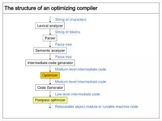
This document presents an approach to optimizing channel parameters for wireless communication, focusing on improving Signal-to-Interference Ratio (SIR) through adaptive modulation, coding schemes, and power level adjustments. Key factors influencing throughput, such as channel load, STA density, interference, and noise properties, are analyzed. The method employs continuous medium monitoring to dynamically adjust channel characteristics, facilitating enhanced data transmission efficiency even in extreme conditions. Additionally, strategies for packet length adaptation are discussed to optimize overall throughput rates when interference is prevalent.

E N D
March 2001 • doc.: IEEE 802.11-01/152 An approach to the problem of optimizing channel parameters Submission Slide 1 Vlad Oleynik, Umbrella Technology
Transmitter Power Level increase Signal-to-Interference Ratio (SIR) Modulation/Coding (BPSK, QPSK, MBOK, CCK, QAM...) in extreme conditions, an modulation/coding scheme with bigger redundancy (lower bit rate) may have better throughput rate Packet Length when interference is present, smaller packet length will decreased PER value Parameters determining potential Throughput Rate for a given medium state Continuous medium monitoring provides the right selection and adjustment of the channel characteristics in real time mode. Slide 2 Vlad Oleynik, Umbrella Technology
Major determination factors • Load level of the communication channel(s) • STA density and topology • Activity Level of WLAN • distortion from other WLAN • Noise Interference properties • Noise bandwidth • Long term / Short term Statistical analyses for medium state To estimate medium conditions, it is possible to use available measurement parameters which depend on both the medium’s state and the communication channel mode. Slide 3 Vlad Oleynik, Umbrella Technology
Medium Changes Adaptation Noise/Interference • To perform medium monitoring it is necessary to have • P sum, summary power level • PhN, phase noise value • PER, time frame statistics G F Packets D E D Phase Noise Threshold Psum A B B A B A A A B A Normal receiving begins. Psum is increased. Phase Noise (PhN) is less then the threshold level B Packet has been transmitted. Psum is decreasing. Phase Noise exceeds the threshold level C Interference. Psum is increased. Phase Noise exceeds the threshold level D Power level of the packet to be transmitted is decreased due to low phase noise level of the previous packet E Power level of the packet to be transmitted is increased due to high phase noise level of the previous packet F Packet was lost because of increasing interference level during packet transmission G Packet was normally received due to high transmission power level Slide 4 Vlad Oleynik, Umbrella Technology
Psum TPC processor Chips Phase Fluctuation PhN CLK Modulation Selector PER Statistics Received Signal Power Level Packet Length Selector Demodulator S DSSS Processor IF MAC S Modulator Techniques of medium adaptation Measured parameters (Psum, PhN, PER) are used to determine the set (S) of the communication channel characteristics (P, PL, Mod) which are optimal for the given regulation strategy. Slide 5 Vlad Oleynik, Umbrella Technology
Techniques of medium adaptation Monitoring: PhN, PER, Psum Transmitter Medium Receiver (P, PL, Mod) Is Medium Yes Changed? PhN Calculation: Psum New No P, PL, Mod PER P, PL, Mod PL P Mod Updated P, PL, Mod Variations in medium state are represented by parameters (Psum, PhN, PER). They are the basis by which to determine the new parameter set S new = (updated Pmin/P, PL, Mod) optimized to the variable medium. Slide 6 Vlad Oleynik, Umbrella Technology
Normal frame transmission + next AP Set @ S(STA) = (P, PL, Mod)STA Techniques of medium adaptation STA adaptation process adaptation process AP AP's transmission @ S(AP) = (P, PL, Mod)AP - Measures PhN, Psum, PER - Determines new AP Set(P, PL, Mod) - Measures PhN, Psum, PER - Determines new STA Set(P, PL, Mod) AP's transmission + next STA Set @ S(AP) = (P, PL, Mod)AP Slide 7 Vlad Oleynik, Umbrella Technology
Transmitter Power Control Initial points for min necessary power level calculation Slide 8 Vlad Oleynik, Umbrella Technology
Transmitter power level adaptation • Transmitter power level adaptation is based on the forecast, which is formed by real time measurement of the propagating condition change • Signal/Interference Ratio (SIR) - interference level changes involve adequate transmitter power level changes • Generating a forecast of the minimum necessary power level is based on RSSI and measurement of phase noise fluctuations, taking into account PER statistics • optimum transmission power level is achieved and maintained • adaptation of the transmitter mode to the typical changes of the medium when affected by changing interferences Slide 9 Vlad Oleynik, Umbrella Technology
Noise/Interference Packets Phase Noise Packets Phase Noise Threshold Packet Length Adaptation When interference is present, smaller packet length corresponds with decreased PER value Slide 10 Vlad Oleynik, Umbrella Technology
Packet Length Adaptation • Adaptation of the packet length is based on analysis of the recent propagating conditions as well as on the cumulative statistics-based forecast for the given modulation/coding and power level • Packet length adaptation to achieve maximum throughput rate is suitable for extreme conditions. • For any extreme condition it is possible to determine the right packet length to provide an advantage in throughput rate Slide 11 Vlad Oleynik, Umbrella Technology
Packet Length Adaptation At a sufficiently high BER value the best average throughput will be achieved by selecting optimal packet length and proper modulation/coding method (not necessarily with max bit rate) . Slide 12 Vlad Oleynik, Umbrella Technology
Zone between - is throughput advantage of 5.5 Mbps (BER 1e-4) vs 11 Mbps (BER 1e-3) Zone between - is throughput advantage of 2 Mbps (BER 1e-4) vs 11 Mbps (BER 1e-3) Packet Length and Modulation/Coding Adaptation For the same medium the BER is different for different modulation methods, and modulations with smaller bit rates may have smaller BER values At a sufficiently high BER value and for each modulation method there is a packet length which provides the maximum Throughput Rate Light magenta zone - is throughput advantage of 1 Mbps (BER 1e-5) vs 11 Mbps (BER 1e-3) Slide 13 Vlad Oleynik, Umbrella Technology
Adaptation of modulation methods • Adaptation of modulation/coding methods is based on analysis of the current state of the medium and propagation condition forecast including multi-path channels for a given power level and packet length • Switching modulation method to achieve maximum throughput rate is suitable for extreme conditions. • For extreme conditions a modulation/coding scheme with bigger redundancy (less bit rate) may have the advantage in throughput rate Slide 14 Vlad Oleynik, Umbrella Technology