Download
1 / 43
450 likes | 918 Vues
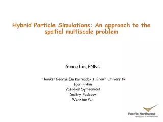
Hybrid Particle Simulations: An approach to the spatial multiscale problem. Guang Lin, PNNL Thanks: George Em Karniadakis, Brown University Igor Pivkin Vasileios Symeonidis Dmitry Fedosov Wenxiao Pan. Flow in heterogeneous porous media. (Darcy flow). Field Scale.

E N D
Hybrid Particle Simulations: An approach to the spatial multiscale problem Guang Lin, PNNL Thanks: George Em Karniadakis, Brown University Igor Pivkin Vasileios Symeonidis Dmitry Fedosov Wenxiao Pan
Flow in heterogeneous porous media.(Darcy flow) Field Scale • Upscaling Approach: MD -> DPD -> Navier Stokes • Hybrid Approach: MD + DPD + Navier Stokes G. Lin, et al, PRL, 2007 Mesoscale Pore Scale Multiphase flow and transport in complex fractures.(Navier-Stokes flow) Microscopic Scale Molecular Scale 2
Numerical Modeling Methods • Upscaling Approach: MD -> DPD -> Navier Stokes • Hybrid Approach: MD + DPD + Navier Stokes DPD SPH
arterioles venules Platelet Aggregation activated platelets activated platelets, red blood cells, fibrin fibers • Platelet diameter is 2-4 µm • Normal platelet concentration in blood is 300,000/mm3 • Functions: activation, adhesion to injured walls, and other platelets
Thrombocytopenic haemorrhages in the skin • Myocardial platelet micro-thrombus
F1dissipative V1 V2 F2dissipative Outline • Dissipative Particle Dynamics (DPD) • Biofilaments: DNA, Fibrin • Platelets • Red Blood Cells • Triple-Decker: MD-DPD-NS
Equilibrium: Static Fluid Symeonidis, Caswell & Karniadakis, PRL, 2005
Shear Flow Symeonidis, Caswell & Karniadakis
Dissipative Particle Dynamics (DPD) • First introduced by Hoogerbrugge & Koelman (1992) • Coarse-grained version of Molecular Dynamics (MD) • Upscaling Approach: MD -> DPD -> Navier Stokes • Hybrid Approach: MD + DPD + Navier Stokes MDDPDNavier-Stokes • MICROscopic level approach • atomistic approach is often problematic because larger time/length scales are involved • set of point particles that move off-lattice through prescribed forces • each particle is a collection of molecules • MESOscopic scales • momentum-conserving Brownian dynamics • continuum fluid mechanics • MACROscopic modeling
rij i j ri rj Pairwise Interactions Fluctuation-dissipation relation: σ2 = 2γκΒΤωD=[ ωR]2 forces exerted by particle J on particle I: Conservative fluid / system dependent Dissipative frictional force, represents viscous resistance within the fluid – accounts for energy loss Random stochastic part, makes up for lost degrees of freedom eliminated after the coarse-graining
DPD MD Conservative Force aij • Linear force From Forrest and Sutter, 1995 • Soft potentials were obtained by averaging the molecular field over the rapidly fluctuating motions of atoms during short time intervals. • This approach leads to an effective potential similar to one used in DPD.
Upscaling Approach The Conservative Force Coefficient: aij The value of aijis determined by matching the dimensionless compressibility1,2 of the DPD system with that of the MD system. From the work of Groot and Warren1, we know for rDPD > 2: 1. R. D. Groot and P. B. Warren, J. Chem. Phys., 107, 4423 (1997) 2. R. D. Groot and K. L. Rabone, Biophys. J., 81, 725 (2001)
F1random F1dissipative V1 V2 F2dissipative F2random Dissipative and Random Forces • Dissipative (friction) forces reduce the relative velocity of the pair of particles • Random forces compensate for eliminated degrees of freedom • Dissipative and random forces form DPD thermostat • The magnitude of dissipative and random forces are defined by • fluctuation dissipation theorem
Upscaling Approach DPD: Coarse-graining of MD • The mass of the DPD particle is Nm times the mass of MD particle. • The cut-off radius can be found by equating mass densities of MD and DPD systems. • The DPD conservative force coefficient a is found by equating the dimensionless compressibility of the systems. • The time scale is determined by insisting that the shear viscosities of the DPD and MD fluids are the same. • The variables marked with the symbol “*” have the same numerical values as in DPD • but they have units of MD. R. D. Groot and P. B. Warren, J. Chem. Phys., 107, 4423 (1997) E.E. Keaveny, I.V. Pivkin, M. Maxey and G.E. Karniadakis, J. Chem. Phys., 123:104107, 2005
Periodic External Force Frozen particles Frozen particles Periodic Boundary Conditions in DPD • Lees-Edwards boundary conditions can be used to simulate an infinite but periodic system under shear • Revenga et al. (1998) created a solid boundary by freezing the particles on the boundary of solid object; no repulsion between the particles was used. • Willemsen et al. (2000) used layers of ghost particles to generate no-slip boundary conditions. • Pivkin & Karniadakis (2005) proposed new wall-fluid interaction forces.
Poiseuille Flow Results: Non-Adaptive BC • Density Fluctuations in MD and DPD MD data taken every time step and averaged over t=100t to t=2000t. DPD data taken every time step and averaged over t=200tDPD to t=4000tDPD. I.V. Pivkin and G.E. Karniadakis, PRL, vol.96, 206001, 2006
Adaptive Boundary Conditions Wallforce Locally averaged density Target density Current density • Adaptive BC: • layers of particles • bounce back reflection • adaptive wall force Iterativelyadjust the wall repulsion force in each bin based on the averaged density values. I.V. Pivkin and G.E. Karniadakis, PRL, vol.96, 206001, 2006
Liquid-like Solid-like Mean-Square Displacement -Large Equilibrium System • The DPD conservative force coefficient a is found by equating the dimensionless compressibility of the systems. • At high levels of coarse-graining the DPD fluid behaves as a • solid-like structure I.V. Pivkin and G.E. Karniadakis, 2006
Multi-body DPD (M-DPD) with Attractive Potential • The interaction forces in M-DPD are: • The dissipative force and random forces are exactly the same as in original DPD, • but the conservative force is modified: A, B are obtained through upscaling process from corresponding MD simulations • Take a negative-valued parameter A to make the original DPD soft pair potential • attractive, and add a repulsive multi-body contribution with a smaller cut-off • radius. S.Y. Trofimov, 2003 Pagonabarraga and Frenkel, 2000 Pan and Karniadakis 2007
M-DPD: Multibody-DPD • M-DPD allows different EOS fluids by prescribing the free energy (DPD fluid has quadratic EOS) • M-DPD has less prominent freezing artifacts allowing higher coarse-graining limit • M-DPD can simulate strongly non-ideal systems & hydrophilic/hydrophobic walls
F1dissipative V1 V2 F2dissipative Outline • Dissipative Particle Dynamics (DPD) • Biofilaments: DNA, Fibrin • Platelets • Red Blood Cells • Triple-Decker: MD-DPD-NS
Intra-Polymer Forces – Combinations Of the Following: • Lennard-Jones Repulsion • Stiff (Fraenkel) / Hookean Spring • Finitely-Extensible Non-linear Elastic (FENE) Spring
FENE Chains in Poiseuille Flow 30 (20-bead) chains side view top view Symeonidis & Karniadakis, J. Comp. Phys., 2006
F1dissipative V1 V2 F2dissipative Outline • Dissipative Particle Dynamics (DPD) • Biofilaments: DNA, Fibrin • Platelets • Red Blood Cells • Triple-Decker: MD-DPD-NS
Interaction with activated platelet, injured vessel wall Activation delay time, chosen randomly between 0.1 and 0.2 s ACTIVATED adhesive PASSIVE non-adhesive TRIGGERED non-adhesive If not adhered after 5 s - passive - triggered - activated Platelet Aggregation RBCs are treated as a continuum Pivkin, Richardson & Karniadakis, PNAS, 103 (46), 2006
- passive - triggered - activated Simulation of Platelet Aggregation in the Presence of Red Blood Cells • Pivkin & Karniadakis, 2007 26
Schematic Model of the RBC Membrane 75 nm • The lipid bilayer is the universal basis for cell membrane structure • The walls of mature red blood cells are made tough and flexible because of skeletal proteins like spectrin and actin, which form a network • Spectrin binds to the cytosolic side of a membrane protein • Spetrin links form 2D mesh • The average length of spectrin link is about 75nm Source: Hansen et al., Biophys. J., 72, 1997 and http://www.lbl.gov/Science-Articles/Archive/LSD-single-gene.html
Motivation and Goal • Spectrin based model has about 3x10⁴ DOFs. It was successfully validated against experiments data, however its application in flow simulations is prohibitively expensive. • In arteriole of 50m diameter, 500m length with 35% of volume occupied by RBCs, we would require 108DOFs for RBCs, and >1011 DOFs to represent the flow. • The goal is to develop a systematic coarse-graining procedure, which will allow us to reduce the number of DOFs in the RBC model. • Together with a coarse-grained flow model, such as Dissipative Particle Dynamics (DPD), it will lead to efficient simulations of RBCs in microcirculation.
0isthe spontaneous curvature anglebetween two adjacent triangles Li is the lengthof spectrin linkiand A is the area of triangular plaquette. Coarse-grain by reducing # of points, N The total Helmholtz free energy of the system: The bending free energy: isthe anglebetween two adjacent triangles The in-plane energy: • Pivkin & Karniadakis, 2007 Worm-like chain: • We need to define: • The spontaneous angle between adjacent triangles, 0 • Persistence length of the WLC links, p • The maximum extension of the WLC links, Lmax • The equilibrium length of the WLC links, L0
Coarse-graining Procedure Fine model Coarse-grained model Nc points, L0c – equilibrium link length Nf points, L0f – equilibrium link length • The shape and surface area are preserved, therefore • The equilibrium length is set as • The spontaneous angle is set as • The properties of the membrane were derived analytically • (Dao et al. 2006) • The persistence length is set as • The maximum extension length is set as • Lcmax=Lfmax (Lc0 / Lf0) Dao M. et al, Material Sci and Eng, 26 (2006)
Coarse-grained ModelShape at Different Stretch Forces Optical Tweezers, MIT 23867 points 500 points 100 points 0 pN 90 pN 180 pN
Deformable RBCs • Membrane model: J. Li et al., Biophys.J, 88 (2005) - WormLike Chain • bending and in-plane energies, constraints on surface area and volume • Coarse RBC model: • 500 DPD particles connected by links • Average length of the link is about 500 nm • Pivkin & Karniadakis, 2007 • RBCs are immersed into the DPD fluid • The RBC particles interact with fluid particles through DPD potentials • Temperature is controlled using DPD thermostat
Simulation of Red Blood Cell Motion in Shear Flow High Low Tumbling Tank-Treading • Pivkin & Karniadakis, 2007
Lonely RBC in Microchannel Experiment by Stefano Guido, Università di Napoli Federico II • Pivkin & Karniadakis, 2007
RBCs Migrate to the Center • Pivkin & Karniadakis, 2007
Experimental Status • Fabrication of 3-6um wide channels • Completed room temperature, healthy runs. Still need to be analyzed. 3mm 4mm 5mm 6mm
Higher concentrations of RBCssimulations • Pivkin & Karniadakis, 2007
Macro-Meso-Micro Coupling NS + DPD + MD
Geometry of Coupling • 3 separate overlapping domains: NS, DPD and MD • integration is done in each domain sequentially • communication of boundary conditions only, not of the whole overlapping region • Fedosov & Karniadakis, 2008
MD-DPD-NS Time Progression Coupling • Fedosov & Karniadakis, 2008 41
Couette and Poiseuille flows • Fedosov & Karniadakis, 2008
Conclusions • We have introduced the upscaling process for defining DPD parameters through coarse-graining of MD and discussed the limitation of DPD • We have presented the difficulties and some new approaches in constructing no-slip boundary conditions in DPD • DPD has been demonstrated to be able to simulate complex bio-fluid, such as platelets aggregation and the deformation of red blood cells. • A hybrid particle model: MD-DPD-NS has been successfully applied to simple fluids.