Download

1 / 59
620 likes | 825 Vues
MPLS FUNDAMENTALS DINESH BHATT Manager (MPLS). Pre-requisites knowledge for understanding MPLS. OSI & TCP/IP layered architecture TCP/IP protocol suite Switch, Router & various protocols they support IP addressing & routing methodology.

E N D
MPLS FUNDAMENTALS DINESH BHATT Manager (MPLS)
Pre-requisites knowledge for understanding MPLS OSI & TCP/IP layered architecture TCP/IP protocol suite Switch, Router & various protocols they support IP addressing & routing methodology
TCP/IP and OSI Model TCP/IP has simple hierarchical design & clear corresponding relations with OSI reference model is as below - 7 Application layer Application layer 6 Presentation layer Session layer 5 4 Transport layer Transport layer 3 Internet layer Network layer 2 Network Interface Data link layer 1 Physical layer Physical layer OSI reference model TCP/IP
IP Addressing & Network Mask 32 bits DottedDecimal Network Host 255 255 255 255 Maximum 32 11111111 11111111 11111111 11111111 Binary 1286432168421 1286432168421 1286432168421 1286432168421 172 16 122 204 IP Add. 10101100 00010000 01111010 11001100 ExampleBinary SubnetMask 255 255 0 0 11111111 00000000 00000000 11111111 Also written as “/16” where 16 represents the number of 1s in the mask. Hence the network of the above IP Add is 172.16.0.0./16
TCP/IP Protocol Stack HTTP, Telnet, FTP, TFTP, Ping, etc Provide application program network interfaces Application Layer Establish terminal to terminal connection TCP/UDP Transport Layer ICMP IP Routing protocols Internet Layer Addressing and route selecting ARP/RARP Ethernet, 802.3, PPP, HDLC, FR, etc Network Interface Layer Physical media access Interfaces and wires/cables Binary data flow transmission Physical Layer
10 Switched Ethernet 10 Hub, Switches Routers Ethernet One device sending at a time. Hub works at layer 1 Hub All nodes share 10 Mbps Multiple devices sending at the same time. Backbone Switch Switch uses MAC address (L2) to filter the network. They do not look at the Network layer header and hence faster (LAN) Each node has 10 Mbps Router Router works at Layer 3, i.e. Network layer, uses IP addresses for facilitating communications amongst the switches or WAN communications ( for which it is connected to other Router)
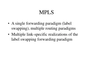
MPLS- Definition • It stands for Multi-Protocol Label Switching. • It is the technique that provides virtual path capability to packet(label) switches. • It aim is to avoid some drawbacks of both circuit switching and packet switching and to increase the utilization of bandwidth. • MPLS is basically deployed to manage the traffic within the ISP . • It combines the benefits of both Circuit switching and packet switching .It uses Circuit switching within ISP. and IP based packet switching within ISPs. • The general idea behind MPLS is to attach a discrete set of labels to IP packets to perform a specific function, without forcing routers and switches to dive into IP addresses or other information in each packet to obtain instructions relating to that particular function. • It efficiently enables Traffic Engineering & quality of service in networks.
Applications 7to5 IP 3 PPP FR ATM (*) Physical (Optical - Electrical) 1 MPLS and ISO model IETF main goal is that when a layer is added, no modification is needed on the existing layers. All new protocol must be backward compatible TCP UDP 4 MPLS PPP Frame Relay ATM (*) 2
MPLS Advantages - • MPLS provides all the required convergence of all type of networks be it IP-network, Next Generation network or our traditional legacy (TDM) network. • By collapsing multiple existing backbone service delivery platform into a single MPLS enable backbone –CONVERGENCE can be achieved. • Reduces CapEx & OpEx by reduction of number of network element. • Increase relaibility. • Seamless Inter-works & Inter-operate with other N/W’s. • IP Rich services can be deployed with minimal CapEx and faster way. • Provides VPN (L3 & L2 intranet, extranet), IPsec, internet.
MPLS: Multi Protocol Label Switching, a Layer 2+ switching, is a versatile solution to address the problems faced by present day Network- Speed, Scalability, Quality of Services(QoS) & Traffic engineering In conventional packet forwarding every router opens the IP datagram and looks at IP header to find out destination IP address and then with the help of its routing table takes independent decision to forward the packet.Handling a bulky IP header and then reconstructing it before forwarding to next router compromises with the speed of entire operation. This operation takes place at layer-3. Unlike conventional forwarding of IP packets, MPLS classifies each packet and attaches a small label with IP datagram at the ingress point of MPLS network. subsequent, routers only look at the label and route the packet after swapping the label with new one. Developed to integrate IP and ATM & Layer-2 protocols (e.g. Ethernet, ATM, PPP, Frame Relay etc.) . Packet forwarding is done based on Labels. Support multiple Layer-3 protocols, such as IP, IPv6, IPX, SNA, OSPF , BGP, static , RIP etc.
MPLS Elements / Terms... LER - Label Edge Router ( PE- Provider Edge) LSR - Label Switch Router (P- Provider or Core Router) FEC - Forward Equivalence Class Label - Associates a packet to a FEC Label Stack - Multiple labels containing information on how a packet is forwarded. Shim - Header containing a Label Stack Label Switch Path - path that a packet follows for a specific FEC LDP - Label Distribution Protocol, used to distribute Label information between MPLS-aware network devices Label Swapping - manipulation of labels to forward packets towards the destination. 11
MPLS Connectionless control plane Connection-oriented forwarding plane Origin: To Integrate IP with ATM IP ATM Connectionless control plane Connection-oriented control plane Connection-oriented forwarding plane Connectionless forwarding plane
S2 1 S6 1 1 S1 S8 S3 S5 2 2 S4 2 S7 Connection-oriented Features S2 S6 S1 S3 S5 S8 VC S4 S7 • connection-oriented: cell switching • VC = S1, S4, S7, S8 • The data reach their destination in order along the same connection • Fixed time delay, easy to control • Connection types: PVC SVC • Connectionless: packet route • Path 1 = S1, S2, S6, S8 • Path 2 = S1, S4, S7, S8 • The data reach their destination out of order along different paths
Traditional IP Forwarding Parse IP header mapped to next hop Parse IP header mapped to next hop Parse IP header mapped to next hop • IP header is parse at each hop, resulting in low efficiency. • It is hard to deploy QoS and the efficiency is rather low. • All routers are expected to know all routes in the entire network.
IP L1 IP L2 IP L3 Basic Working Process of MPLS Core LSR Edge LSR Edge LSR IP IP Traditional IP forwarding Traditional IP forwarding Label forwarding
LER MPLS domain IP LER LSR LSR LER LSP LSR MPLS LER Basic MPLS Concepts LSR: Label Switch Router LER: Label Edge Router LSP: Label Switch Path
A packet can be mapped to a particular FEC based on the following criteria: • destination IP address, • source IP address, • TCP/UDP port, • in case of inter AS-MPLS, Source-AS and Dest-AS, • class of service, • application used, • … • any combination of the previous criteria. Ingress Label FEC Egress Label 6 138.120.6/24 - xxxx 9 Ingress Label FEC Attribute Egress Label Ingress Label FEC Attribute Egress Label • FECs are manually initiated by the operator 6 138.120.6/24 - xxxx A 9 • A FEC is associated with at least one Label 6 138.120.6/24 - xxxx B 12 FEC Classification
MPLS Encapsulation Format and Label 0 20 23 24 31 32 bits Label EXP S TTL Layer 2 header MPLS header IP header Data • Two types of MPLS encapsulation for ATM and FR: • shim encapsulation: similar to other link layers • Cell mode: VC (VPI/VCI for ATM, DLCI for FR) is directly used as the label Label : Label value Exp : Experimental Use ( Class of Service) S : Bottom of Stack (set to 1 for the last entry in the label) TTL : Time To Live
MPLS TTL Processing Regard the entire MPLS domain as one hop IP TTL -- MPLS TTL=255 MPLS TTL -- IP TTL -- Ingress LER LSR Egress LER Include MPLS TTL in IP TTL IP TTL -- MPLS TTL=IP TTL MPLS TTL -- MPLS TTL -- IP TTL=MPLS TTL Ingress LER LSR Egress LER
Label Position in Packet Ethernet /SONET /SDH packet Ethernet header /PPP header Label Layer-3 data Frame mode ATM packet ATM header Label Layer-3 data Cell mode ATM packet VPI/VCI Layer-3 data
Label Stack Layer2 header MPLS header MPLS header IP header Data Theoretically, label stack enables limitless nesting to provide infinite service support. This is simply the greatest advantage of MPLS technology.
Ingress Interface Ingress Label Egress Label FEC Egress Interface Ingress Interface Ingress Label Egress Label 12 FEC Egress Interface 5 12 1 4 138.120 x 1 3 138.120 Ingress Interface Ingress Label Egress Label FEC Egress Interface 5 1 x 3 138.120 Label Switched Path MPLS switch 3 1 138.120 4 1 2 MPLS switch 3 127.20 1 2 3 3 MPLS switch 192.168 2 1 2 MPLS switch
Ingress Interface Ingress Label Egress Label FEC Egress Interface Ingress Interface Ingress Label Egress Label FEC Egress Interface 1 Default 4 None x 1 Default 3 Default None ?? ?? MPLS switch ?? ?? 3 1 138.120 4 1 2 MPLS switch 3 127.20 1 2 3 3 MPLS switch 192.168 138.120.6.12 138.120.6.12 138.120.6.12 138.120.6.12 138.120.6.12 138.120.6.12 138.120.6.12 138.120.6.12 138.120.6.12 138.120.6.12 138.120.6.12 138.120.6.12 ?? ?? 2 1 2 MPLS switch Ingress Interface Ingress Label Egress Label FEC Egress Interface 1 x 3 Default None Hop by Hop IP forwarding
Ingress Interface Ingress Label Egress Label FEC Egress Interface Ingress Interface Ingress Label Egress Label FEC Egress Interface 12 1 5 4 12 138.120 x 1 3 138.120 138.120.6.12 138.120.6.12 138.120.6.12 138.120.6.12 138.120.6.12 Ingress Interface Ingress Label Egress Label FEC Egress Interface 5 1 x 3 138.120 IP forwarding using LSP MPLS switch 3 1 138.120 4 1 2 MPLS switch 3 127.20 1 2 3 3 MPLS switch 192.168 2 1 2 MPLS switch 24
Basic Concepts of Label Forwarding • FEC (Forwarding Equivalence Class): Import the packets with identical characteristics into the same LSP • NHLFE (Next Hop Label Forwarding Entry): Describe label operations • next hop • label operation types: push/pop/swap/null • Link layer encapsulation types • FTN (FEC to NHLFE): Map FEC to NHLFE • ILM (Incoming Label Map): Map MPLS label to NHLFE
Label Forwarding Stack label operation: pop Label operation: push ILM->NHLFE Parse IP header distribute FEC mapped to next hop Label operation: swap Label operation: swap Parse IP header FEC bound with LSP FTN->NHLFE ILM->NHLFE ILM->NHLFE A B C D Egress LER Ingress LER LSR LSR • The traditional routing protocol and Label Distribution Protocol (LDP) serve to create routing table and label mapping table (FEC-Label mapping) in each LSR for FECs with service requirement, i.e. create LSP successfully. • Ingress LER receives a packet, determines the FEC that the packet belongs to, and label the packet • In MPLS domain, packets are forwarded in accordance with labels and label forwarding table via the forwarding unit • Egress LER removes the label and continues forwarding the packet
NHLFE A: FEC NHLFE Label operation Others next hop Transmitting interface 10.0.1.0/24 E1 Add label L1 … B B: NHLFE Ingress label Transmitting interface Next hop label operation Others L1 C E1 … Remove the previous label and add L2 C: NHLFE Ingress label Others Transmitting interface Next hop Label operation E1 L2 D Remove label …
Pop at Last Hop But One (PHP) Label operation: push Label operation: swap • The label at the outmost layer does not make any sense to the last hop. Thus, it is advisable to pop the label at the last hop but one to ease the burden of the last hop. • If there is only one layer of label, the last hop will perform IP forwarding directly; otherwise, it will perform the internal label forwarding. Parse IP header Distribute FEC Mapped to next hop Label operation: pop Parse IP header FEC bound with LSP FTN->NHLFE ILM->NHLFE ILM->NHLFE LSR Ingress LER LSR Egress LER
Creating LSP • LSP drive modes: • Driven by stream: incoming packets drive LSP creation • Driven by topology: topology information (route) drives LSP creation • Driven by application: application (like QoS) drives LSP creation • Signaling protocol is used to distribute labels between LSRs and establish LSP: • LDP: Label Distribution Protocol • CR-LDP: Constrained Route LDP • RSVP-TE • MP-BGP • PIM
Several Issues Concerning Label Distribution • Label allocation mode • DoD : downstream-on-demand • DU: downstream unsolicited • Label control mode • Ordered • Independent • Label hold mode • Conservative retention mode : upon receiving a label, if there is no route destined for the corresponding FEC, hold the label for later use • Liberal mode: upon receiving a label, if there is no route destined for corresponding FEC, discard the label
Label 18 is allocated to 171.68.10/24 171.68.10/24 171.68.10/24 分配到 分配到 Label 20 is allocated to 171.68.10/24 20 18 的标签为 的标签为 Label Allocation Mode: DoD Route triggering 171.68.40/24 171.68.10/24 LSR1 LSR2 LSR3 Downstream Upstream Requesting labels destined for 171.68.10/24 请求到目的地址 Requesting labels destined for 171.68.10/24 171.68.10/24 的标签 的标签 The upstream LSR sends a label request (containing FEC description information) to the downstream LSR. The downstream LSR allocates a label to this FEC and feeds back the bound label to the upstream LSR via the label mapping message.
171.68.10/24 到 Label 18 can be used to reach 171.68.10/24 Label 20 can be used to reach 171.68.10/24 20 可以使用标签 Label Allocation Mode: DU Route triggering Downstream Upstream 171.68.40/24 171.68.10/24 Once the LDP session is set up successfully, the downstream LSR will initiatively advertise the label mapping message to its upstream LSR. The upstream router will save the label in the label mapping table.
Label Control Mode: Ordered Not until it receives a label mapping message from its downstream LSP will it send the message upstream DOD+ Ordered Downstream Upstream DU+ Ordered Downstream Upstream
Label Control Mode: Independent Whether it receives a label mapping message from its downstream LSR, it will send upstream a label mapping message immediately. DOD+ independent Downstream Upstream DU+ independent Downstream Upstream
Label Retention: Conservative Retention Mode • An LSR stores only the labels received from next-hop LSRs; all other labels are ignored. mapping label 20 mapping label 30 172.16.2/24 mapping LSR2 LSR3 LSR1 LSR4 label 16 mapping label 17 Drop LSR5
Label Retention: Liberal Retention Mode • Every LSR stores the received label in its LIB, even when the label is not received from a next-hop LSR. mapping label 20 mapping label 30 172.16.2/24 mapping LSR2 LSR3 LSR1 LSR4 label 16 mapping label 17 store LSR5
Common Collocation 2: DU + Ordered + Conservative Upstream Downstream • A waste of label resources • Useless LSPs would be created • Label merge is required at branches • LSPs can be set up quickly and reliably
Common Collocation 1: DoD + Ordered + Liberal Downstream Upstream • It is relatively easy to control the use of labels and the creation of LSPs • ATM/FR frame mode can only use DoD
Label Forwarding Table • The “in” and “out” is correspond to the label swap,not the label distribution. • The in label is that I distribute to the others, I will not put it to the packet • The out label is the others distribute to me, I will put it to the packet
LSP Loop Detection • Path looping shall be avoided even in setting up LSP within the MPLS domain. • LSP path looping can be avoided in two ways: • Maximum hop number; • Path vector
Basic Concepts of LDP • LDP is a MPLS control and signaling protocol • Main functions: • Release Label-FEC mapping • Create and maintain label switching path • LDP serves to distribute and maintain label mapping messages between peers in the form of message. • LDP uses the TCP transmission service.
LDP Message Types • Discovery message: Used to discover LDP adjacencies in the network • Session message: Used to set up, maintain and terminate a session between LDP peers • Distribution message: Used to create, change and delete label mappings related to FEC • Notification message: Used to provide recommendation or error notification information
UDP-Hello UDP-Hello Session initialization Label request FEC Label Label mapping LDP Message Switching Discovery stage TCP connection establishment Session creation and maintenance LSP creation and maintenance
Basic MPLS Configurations (1) • Designate ID for LSR It is necessary to configure the LSR with an ID before configuring other MPLS commands. The ID is generally in the format of IP address, and shall be unique within the domain. mplslsr-id X.X.X.X Note: make configurations in the system view. • Activate/deactivate the LDP or enter the LDP view To configure LDP, first activate the LDP and enter the LDP view mplsldp Note: make configurations in the system view
Basic MPLS Configurations (2) • Enable interface LDP mplsldp enable Note: make configurations in the interface view • LDP loop detection control • Enable loop detection Loop-detect • Set the maximum hot number for loop detection hops-count hop-number • Set the maximum value for the path vector path-vectors pv-number Note: make configurations in the LDP view
MPLS Debugging • MPLS display commands • Display information about LDP and LSR display mplsldp • Display information about LDP-enabled interface display mplsldp interface • Display information about all LSPs established in the public network display mplslsp
Router B ethernet1/0/0 ethernet1/0/1 Router A Router D 168.1.1.2 172.17.1.1 pos2/0/1 ethernet2/0/1 ethernet8/0/0 100.10.1.2 172.17.1.2 168.1.1.1 pos7/0/0 100.10.1.1 Router C Configuration Example • Suppose a network consists of four NE routers, where Router B is connected to Router C via SDH, while Router B is connected to Router A and Router D via Ethernet. • The four routers all support MPLS. LSP can be set up between any two routers. The operational routing protocol is OSPF Router C is configured with: [Quidway] interface pos 7/0/0 [Quidway-Pos7/0/0] ip address 100.10.1.1 255.255.255.0 [Quidway] router id 172.16.1.2 [Quidway] ospf [Quidway-ospf] area 0 [Quidway-ospf-area-0.0.0.0] network 100.10.1.0 0.0.0.255 [Quidway] mpls lsr-id 172.16.1.2 [Quidway] mpls ldp [Quidway-Pos7/0/0] mpls ldp enable • Configuration procedure • Configure ip address for the interface • Configure the ospf protocol • Configure the MPLS LDP ip route-static 171.68.0.0 255.255.0.0 Serial0 ip route-staticvpn-instanceVPN-A 0.0.0.0 0.0.0.0 192.168.1.1 public
MPLS VPN Network Structure VPN_A VPN_A VPN_A VPN_A iBGP sessions 11.5.0.0 10.2.0.0 10.2.0.0 10.2.0.0 CE CE CE CE VPN_B VPN_B VPN_A 10.1.0.0 P P 10.2.0.0 10.2.0.0 PE CE PE PE CE CE VPN_A VPN_A 11.6.0.0 11.6.0.0 P P CE CE VPN_B PE CE 10.3.0.0 PE PE VPN_B VPN_B CE CE 10.1.0.0 10.1.0.0 • CE (Custom Edge): The user equipment directly connected with the service provider. • PE (Provider Edge Router): The edge router on the backbone network, connected with CE and mainly responsible for access of the VPN service. • P (Provider Router): The core router on the backbone network, mainly responsible for the routing and fast forwarding functions.