Download
1 / 1
10 likes | 103 Vues
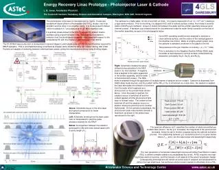
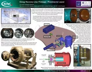
Cathode Ball at -350 kV. Ceramic Insulator. Electrons. Laser Beam. SF 6 Pressure Vessel. Anode Plate at 0 V. Energy Recovery Linac Prototype - Photoinjector Layout. L. B. Jones, Accelerator Physicist.

E N D
Cathode Ball at -350 kV Ceramic Insulator Electrons Laser Beam SF6 Pressure Vessel Anode Plate at 0 V Energy Recovery Linac Prototype - Photoinjector Layout L. B. Jones, Accelerator Physicist. The Cockcroft Institute, Daresbury Science and Innovation Campus, Warrington, WA4 4AD, United Kingdom. The ERLP photoinjector utilises a GaAs semiconductor wafer, activated to a state of Negative Electron Affinity (NEA), such that electron emission can be driven by a laser operating at visible wavelengths. It is a copy of the Jefferson Laboratory IR-FEL injector. The NEA state is attained through the application of multiple layers of caesium and an oxidant. This both lowers the work function of the surface and increases the electron yield per laser pulse (known as the quantum efficiency). The cathode assembly is held at -350 kV and is electrically isolated by the largeceramic insulator visible in the lower-left photograph. A Pierce-type anode plateis located 10 cm in front of the cathode ball. Electrons emitted from the cathodeare thus accelerated to 350 keV, and are then further accelerated to 8.35 MeV inthe superconducting RF booster module located immediately after thephotoinjector, to preserve the low emittance of the injector. Drive Laser Optical Table Above: The photoinjector pressure vessel, showing the back of the gun assembly. The cathode retraction mechanism and electrical connections for the charge collector and caesium dispensers are visible. To activate the cathode, it is first retracted inside the ball. The cathode wafer is then cleaned by heating to desorb contaminants from its surface. The wafer is illuminated with a light source, and an electrical current passed through the caesium dispensers to stimulate emission of caesium. The oxidant is introduced through a leak valve on top of the gun chamber. Electrons photo- emitted during the procedure are attracted to the positively-biased charge collector and register as a photocurrent. This is used to monitor progress during wafer activation, and to assess the ultimate quantum efficiency attained. Above: The photoinjector drive laser system delivers 10.5 W at 1064 nm (infra-red) and is later frequency-doubled to 532 nm (visible green). The output is mode-locked, yielding pulses of 7 ps duration at a repetition rate of 81.25 MHz. 1 3 2 2 3 Photoinjector Laser Beam Transport System 500 kV DC Power Supply Above: Views inside the cathode ball, which contains the apparatus required to activate theGaAs cathode wafer. These are the charge collector (1) and caesium dispensers (2). Theflap (3) is used to protect the cathode during high voltage conditioning. Below: The photoinjector gun assembly, showing the ceramic insulator, the cathode support tube and the cathode ball. The GaAs cathode wafer is mounted on the emitter assembly tube which fits inside the cathode support tube. The cathode fills the hole at the front of the cathode ball where it is exposed to the drive laser. Superconducting RF Accelerating Module Above: Schematic showing the gun assembly inside its pressure vessel, and the anode plate. The pressure vessel contains SF6 gas for insulation. Above: The 500 kV power supply pressure vessel, showing the Cockcroft-Walton multiplier.