Advanced Modulator Development: Testing, Construction, and Results - Howie Pfeffer
Explore the latest findings in testing and development of modulators by Howie Pfeffer, including 3-cell testing results, 9-cell construction updates, specifications, waveform analysis, and special considerations. Enhance your knowledge in modulator technology.

Advanced Modulator Development: Testing, Construction, and Results - Howie Pfeffer
E N D
Presentation Transcript
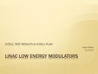
3-CELL TEST RESULTS & 9-CELL PLAN Howie Pfeffer 11/13/13 LINAC LOW ENERGY MODULATORS
900 V/cell, 8.3 ohm load – no problem?! 3-Cell test
Turn-on Ringing, cells switching within 600ns 3-cell test
Run just 2-cells - simplify Bottom (ground-level) cell switching in 2nd place – measurements easier. Isolated charging circuits with high-value resistors – eliminate other possibilities. Still had oscillations when spaced less than 600 ns. investigating
Turn-on Ringing, cells within 600ns 2-cell testing
After various failures, started to suspect problem due to diode turn-off before diode is fully on. Seen similar problems with FETs – turning them off shortly after turning them on. If so, then problem should go away if diode is at higher current during turn-off. Possible explanation?
Switching at 300 amps 2-cell
Switching at low currents 2-cell
“ON” time is important 2-cell
3-cell switching at 100 amps 3-cell
No problems with 3-cell operation as long as initial turn on timing is done properly. Simultaneous turn-on yields 2700 volts with 250 ns rise time (10% - 90%). 9-cell construction under-way 3-cell testing conclusions
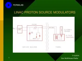
Modulator requirements Pulse rep rate: 15 Hz Maximum Output: 35 kV Maximum step size: 1.5 kV Load Resistance: ~100 ohm Beam Length/Time: 110 usec Load (Tube) Voltage 40-Cell Marx Output Beam Top Tilt (Adj.): +/- 5 kV Beam Voltage Step : 15 kV/usec Flattop/Beam Reg.: +/- 25 V Repeatability: +/- 10 V Max. sparkEnergy: < 5 Joules 12-Cell Reg. Output
Nine steps up to 8 kV • Load = 100 ohms. • First step on for 2 us before subsequent steps. • One step followed by 8 cells simultaneously. • Uses existing driver electronics. • Delays between control edges and outputs. • Short circuit protection • Delay turn-off by 8 us after receiving trip signal. This allows overcurrent circuits on gating boards to turn off slowly. 9 – cell testing
Interleaved Regulator operation • Uses Matt’s circuit. • Doesn’t require ultimate resolution. • Pulse one cell ON, then make 4 kV 8-cell interleaved pulse. • 1 us spacing, 2 us minimum time, 8 us cycle, 96 us pulse length. • Filter circuit? • Short circuit response • Freeze signals for 8 us then turn OFF. 9 – cell testing (cont.)
9-cell test waveforms Program Voltage Triangle Square Wave Load Voltage
Pwm filter Filtered Unfiltered
Short circuit testing • Critical function – there will be arcs • Charging diode transients during pulse • Diode Qrr results in reverse current during turn-off • Charge inhibit function • Ensure charge switch and main switch are never on at the same time - disaster Special concerns
Short circuit concerns SPARK CURRENT AND ENERGY WITH NO CURRENT LIMITTING 55 Joules (50 volt arc) 37,000 amps 18 usec
Importance of charge inhibit Main Switch Capacitor Charged to 950 volts Charging Switch Current
9-Cell construction on-going • All 9 cells individually tested • Controls for ramping complete • Regulation mode controls being designed • Goal: start system testing in late January Conclusions, 9-cell testing