Silicon Optical Modulators
Silicon Optical Modulators. Recent developments in fabrication of High Speed Modulators J ee290f. Outline. Motivation Png, Reed, et al. work from Surrey. Shows basic principle and gives one of the two major design types Intel device

Silicon Optical Modulators
E N D
Presentation Transcript
Silicon Optical Modulators Recent developments in fabrication of High Speed Modulators J ee290f
Outline • Motivation • Png, Reed, et al. work from Surrey. • Shows basic principle and gives one of the two major design types • Intel device • History making device, designed and fabricated in alternate major design type. • Conclusions
Motivation • Very clear: Si modulators means CMOS integration and using all our experience in silicon micromachining. • Unfortunately, prior to 2003 the fastest Si optical modulator was ~20MHz (Lithium Niobate modulators are ~10GHz).
p-i-n Si Optical Modulators 1/4 • Follows the work presented by Png, Reed, et al from Surrey University (UK).
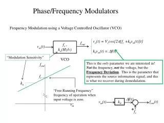
p-i-n Si Optical Modulators 2/4 VD is applied to Anode vs. Cathode. → forward biased p-i-n junction. → e and holes injected into guiding region → changes refractive index
p-i-n Si Optical Modulators 3/4 n = ne + nh = -[8.8 x 10⁻²²(Ne) + 8.5 x 10⁻¹⁸(Nh)0.8] = e + h = 8.5 x 10⁻¹⁸ (Ne) + 6.0 x 10⁻¹⁸(Nh) From R.A. Soref & B. R. Bennett “Electrooptical Effects in Silicon” Jour. Of Quan. Elec. 1987.
p-i-n Si Optical Modulators 4/4 • Simulation results show modulation can be optimized to 1.3GHz and a 180 at .7 mA of current. • However, performance is very dependant on doping profile and a critical dimensions are not very tolerant. • As of late 2003, fabrication is underway.
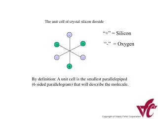
MOS Si Optical Modulators 1/4 • Still uses the plasma dispersion effect, but implements a MOS capacitor to induce change in free carrier density instead of a p-i-n device. • Again designed for single mode 1.55m.
MOS Si Optical Modulators 2/4 Apply VD to poly. Charge accumulation on both sides of gate oxide. Ne = Nh = [/etoxt]*(VD – VFB) ne = -8.8 x 10⁻²²Ne nh = -8.5 x 10⁻¹⁸(Nh)0.8 = (2/)neffL
MOS Si Optical Modulators 3/4 • Implemented phase shifter in both arms of a MZI. • For VD = 7.7V → 16dB total switch. • Loss is the big key: ~15.3dB insertion loss (~4.3dB from coupling & ~6.7dB from poly guides).
MOS Si Optical Modulators 4/4 Switching test on psuedo-random time signal. See 3dB roll off at >1GHz from MOS cap.
Conclusion • MOS modulator has poor loss figures and still an order of magnitude slower than commercial modulators. Intel argues these can both be theoretically fixed by decreasing the size of the device and using Si in the guide region instead of poly (still integrable?). • P-i-n modulator is still being fabricated and depends on its optimal design for the high values achieved, so potentially success or failure from fabrication runs.