Understanding Piezoelectric Properties in Crystalline Quartz and Device Design
This text explores the piezoelectric and converse piezoelectric properties of crystalline quartz, emphasizing their applications in designing electro-mechanical devices. It discusses how mechanical forces can generate electrical signals, and vice versa, highlighting the significance of mechanical resonance frequencies in device performance. The text provides insight into unit cell behavior under various mechanical stresses, definitions of frequency, and design considerations for building crystals that operate at specific resonance frequencies.

Understanding Piezoelectric Properties in Crystalline Quartz and Device Design
E N D
Presentation Transcript
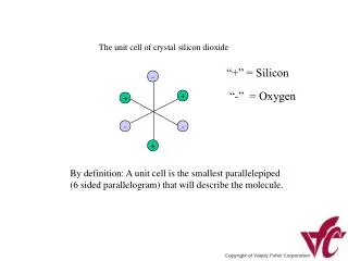
“+” = Silicon “-” = Oxygen By definition: A unit cell is the smallest parallelepiped (6 sided parallelogram) that will describe the molecule.
- + + - - + - + + - - + + + + Unit Cell Under Mechanical Compression (“pushing” force): Electrical polarity as shown Unit Cell at Rest - - - - - - Neutral Charge Unit Cell Under mechanical Tension (“pulling” force): Electrical polarity reverses. + + + +
- + + - + - - + + - - + 2 compression forces in opposite directions…... Unit Cell at Rest + + + - - - Neutral Charge Will also result in electrical energy! This is called a shear force, and is the most common mechanical distortion in crystals we make: This is where the famous term: Thickness Shear has its origins….-AT, -BT, & SC crystals all are shear mode devices (more on this later)
What we have learned so far …. • The unique piezoelectric and converse piezoelectric properties of crystalline quartz allow us to design an electro-mechanical device (mechanical force = electrical signal; electrical field = mechanical deformation) • By operating the device at its mechanical resonance frequency, we can get a useful electrical signal out of it: The electrical signal will be at the same frequency as the mechanical resonance frequency. • If we know how to control the devices mechanical resonance frequency, we ought to be able to design a device at any frequency of interest…..
Definition of Frequency…. • For purposes of this class, the term frequency refers to a mathematical description of a periodic (or repeating) signal. • Since all of the devices we build at VF are designed to produce a very stable frequency signal, we can analyze a typical output signal to get a general feeling how the signal behaves.
Anatomy of a Sine Wave and a Square Wave Sine Wave Square Wave
Amplitude, pk to pk Time Wavelength Period Amplitude: A measure of how big the signal is. Usually expressed in Electrical Units (voltage or current). Wavelength: How long the signal is (usually in meters). Period: How much time it takes to complete 1 cycle (measured in seconds). Frequency: The number of complete cycles in a 1 second chunk of time. Frequency is equivalent to 1/Period, and is commonly measured in Hertz; 1 Hz = 1 cycle per second
Now, we should have enough information to allow us to design a crystal. We will build an y-cut extensional vibrational mode crystal that will operate at a fundamental resonance frequency of 50 kHz... Same crystal with driving signal applied, operating in length extension mode. Electrode Crystal at rest Wires for circuit attachment Extensional Mode is the $5.00 term meaning the part gets longer when an electrical field is applied (remember: E field = mechanical deformation!). We also need a pair of electrodes to connect to a circuit: These are simply a couple of conductive plates attached to the major faces of the crystal.
First, you need to know how to reference the crystal out of the raw crystal stone. Both X-cut and Y-cut crystals are simply cut parallel to their respective axes (more complicated cuts require x-ray technology to locate the crystal axis orientation) z x y
For the case of an X-cut or Y-cut, the resonance frequency is related to the geometry of the blank by a 1/2 wavelength ratio. This is similar in nature to the xylophone, where each metal bar is tuned to an audible tone. I offer the following mathematical relationship without proof so as to avoid confusion. I have provided this proof in the class notes I sent out to everyone. For now, just take my word for it…... “fx” is the frequency in the x direction. “n” is the harmonic order (don’t worry about this for now). “t” is the thickness of the crystal. “kx” is known as the “frequency constant” in the x direction. “fy” is the frequency in the y direction. “n” is the harmonic order (don’t worry about this for now). “l” is the length of the crystal. “ky” is known as the “frequency constant” in the y direction.
“fx” We want 50 kHz. “n” = 1, for fundamental mode. “l” is the thickness of the crystal. “ky” In the Y direction, this is 2600 kHz-mm PROBLEM 1 “fx”: We don’t want the crystal to vibrate in the x (thickness) direction at all! This may cause interference with the vibration in the x direction. Also, the frequency constant is different in the x direction (2870 kHz-mm) This is due to the anisotropic nature of quartz: That is, due to the crystalline molecular structure, some physical properties of the device change with direction.
One clever way around this dilemma is to change the aspect ratio so that the dominant resonance is in the direction of interest. “Aspect ratio” is engineer-ese for the length-to-thickness ratio, in this case. EXAMPLE: For an aspect ratio of 10:1, a 10 mm length has a 1 mm thickness…. Let’s take a guess and make the length 10 times the width… And begin the design:
This is about 2 inches, so with an aspect ratio of 10:1, the thickness will be 5.2 mm, or about 0.2”
Since we have not put any restrictions on the Z axis (which is the width), we can choose to go with a convenient value that will take other design aspects into account. Lets say that the only electrodes available to us are 0.35” …… 0.35” = 9 mm. Now, we can simply make the Z width something slightly larger. Lets try a length to width aspect ratio of 5 (eg: length is 5 times the width). This width should work fine for our 9 mm electrode.
Summary of the finished design Length: 52.0 mm (2.05”) Width: 10.4 mm (0.41”) Thickness: 5.2 mm (0.20”) Electrode W.: 9.0 mm (0.35”) Elec. l t w