Download
1 / 1
10 likes | 117 Vues
Discussing the setup and operation of a high-energy photoinjector prototype used in an Energy Recovery Linac system for accelerator physics research. Detailed explanation of the cathode activation process, laser technology, and operating conditions. Importance of maintaining clean cathode surface and controlling residual gases. Future implications for Free Electron Lasers utilizing high-brightness electron beams. Ongoing research and development for FEL applications in accelerator-based light sources.

E N D
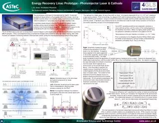
D2O 10000 H2O Wada 1000 1/e Lifetime [sec] 100 10 1 10-10 10-8 10-9 10-7 10-6 Partial pressure, water [mbar] Energy Recovery Linac Prototype - Photoinjector Laser & Cathode L. B. Jones, Accelerator Physicist. The Cockcroft Institute, Daresbury Science and Innovation Campus, Warrington, WA4 4AD, United Kingdom. The cathode is a GaAs wafer, 32 mm Ø and 625 mm thick. It is heavily-doped with Zn at ~2 × 1019 cm-3 creating ap-type semiconductor. Prior to mounting, it is dipped in HCl acid to remove surface oxides, then rinsed in several baths of 99.9% pure methanol. A layer of indium foil between the wafer and the emitter assembly ensures good thermal contact. A tantalum cup crimped around its circumference holds the wafer firmly in position on the end ofthe emitter assembly, as seen in the photographs below. The photoinjector drive laser is manufactured by HighQ. It uses two neodymium-doped yttrium orthovanadate (Nd:YVO4) diodes, one in an oscillator and the other in an amplifier cavity. It is mode-locked to deliver 1064 nm radiation in 7 ps pulses at an 81.25 MHz repetition rate. It is actively phase-locked to the ERLP low-level RF system master oscillator using a synchronisation unit. This ensures that electron emission from the photoinjector is appropriately timed with respect to the accelerating RF, with the measured jitter being less than 400 fs. Good XHV operating conditions are essential to maintain a clean cathode surface, and the nature of the residual gases in the chamber are critical. Water is a highly-potent poison once the cathode is activated, as shown in the graph to the left. Total pressure in the gun chamber is routinely < 2 × 10-11 mbar. Prior to activation to the Negative Electron Affinity (NEA) state, the wafer is heat-cleaned to remove surface contaminants by desorption, principally Ga2O, Ga2O3 and As2O3. The 81.25 MHz laser pulse-train is manipulated in several stages to yield single-pulse to 100 ms macrobunches required for ERLP operation. This is accomplished using a mechanical chopper and a shutter to carry out ‘coarse’ slicing, with a fast Pockels cell capable of switching between individual laser pulses, giving the macrobunches sharp rising & falling edges. Right: Schematic showing the setuputilised during activation to the NEAstate in our test chamber. A negativebias is applied to the wafer supportedin the emitter assembly, and the waferis illuminated with a laser. The NEAstate is obtained through the application of multiple layers of caesium and an oxidant. Caesium is dispensed from SAES alkali metal sources, and the oxidant (either NF3 or O2) is introduced via a leak valve. As caesium is applied, Webscope to monitor status of laser system the laser stimulates the emission of electrons from the wafer which registers as a photocurrent on the picoammeter shown above. Once the peak is reached, the caesium source is switched off and the oxidant applied until the photocurrent falls back to its base value. The oxidant is then switched off and the caesium source re-started, driving the photocurrent to another higher peak. As the activation progresses, the photocurrent peak value iterates towards a maximum, as shown in the plotter trace reproduced to the right. Peak current: 770 nA Dark Current: 90 nA Photo current: 680 nA Laser power: 45 mW Laser wavelength: 532 nm Q.E. = 3.5% 532 nm driving beam plus 1064 nm timing beam to photoinjector Above: Schematic layout of the drive laser and optical components for beam manipulation. Left: Schematic showing how the laser pulse- train is manipulated to yield the pulse structure required for the ERLP Below: A comparison between the radiation generated in CW and mode-locked lasers with a cavity length of L. The quantum efficiency (Q.E.) specifies the number of electrons emitted per incident laser photon. As the Q.E. increases, the magnitude of the photocurrent increases, hence its use to monitor progress during the cathode activation process. The relationship between Q.E. and photocurrent (I) is given below, where Plaser and l are the laser power and wavelength respectively. dn= c/2L The next generation of accelerator-based light sources will utilise Free Electron Lasers(FEL) to deliver tuneable radiation at unsurpassed flux levels. A FEL requires very high-brightness electron bunches, and this impacts on all aspects of the parent accelerator design. Consequently, photoinjectors will remain an active area of research and development to deliver the high-brightness, low-emittance electron beam needed to effectively drive a FEL. Time