Download
1 / 23
260 likes | 503 Vues
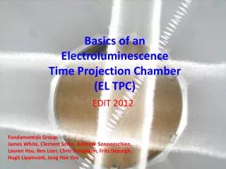
Basics of an Electroluminescence Time Projection Chamber (EL TPC). EDIT 2012 . Fundamentals Group: James White, Clement Sofka , Andrew Sonnenschien , Lauren Hsu, Ben Loer , Chris Stoughton, Fritz Dejongh , Hugh Lippincott, Jong Hee Yoo. LESSON.

E N D
Basics of anElectroluminescence Time Projection Chamber(EL TPC) EDIT 2012 Fundamentals Group: James White, Clement Sofka, Andrew Sonnenschien, Lauren Hsu, Ben Loer,Chris Stoughton, Fritz Dejongh, Hugh Lippincott, Jong HeeYoo
LESSON • Concept of Electroluminescent Time Projection Chamber (EL TPC) – uniform drift field and parallel plate EL gap • Scintillation mechanism in noble gases • Electron drift and diffusion in gases • Electroluminescence: aka light gain / proportional scintillation • Estimate charge yield of alpha in argon gas • Estimate EL yield • Will study the concept using a toy: ”EL TPCito”
EL TPC Physics Detectors • ZEPLIN II/III two-phase xenon WIMP search • XENON 10/100 two-phase xenon WIMP search • LUXtwo-phase xenon WIMP search • WARP two-phase argon WIMP search • DarkSidetwo-phase argon WIMP search • PANDA-X two-phase xenon WIMP search • NEXT-100 high pressure xenon 0νββ search • many other prototypes for reactor monitoring, homeland defense, medical …
ConceptHow does it work? Gamma (for example) Light detectors Anode EL Gap Electroluminescence (S2) Gate Electron drift Interaction and Drift Region E-field Deposits energy Flash of scintillation (S1) Cathode Time S1 S2
Example: LUX 50 cm 50 cm
60 keV Gamma e.g. High Pressure Xenon TPC Neutron (or WIMP) S1 S2 30 keV e- 30 keV X-ray 30 keV e-
Why use an EL TPC? NR discrimination Tracking 137Cs electron recoils 662 keV nuclear recoils 241Am 30 keV Energy Resolution
Scintillation Mechanisme.g.Argon ~1 bar (Similar in other noble gases) Atom excited by particle interaction: Ar* + 2Ar Ar2* + Ar Ar2* 2Ar + hν And, recombination can produce light: Ar+ + e- Ar* 128 nm
Argon Scintillation (cont) Fast component (singlet) Penning effect Slow component (triplet) Example of alpha-induced scintillation (S1) in pure argon at P ~ 50 bar with zero drift field. (Summed pulses from a high pressure test cell at TAMU.) Similar, but single event with a trace of xenon. Interaction with impurity atoms greatly alters pulse shape.
Electron Drift With no electric field, liberated electrons will obtain a Boltzmann energy distribution E ~ kT - some will recombine with the positive ions. With an electric field E present, electrons will drift with velocity v ~ µ E, where µ is the electron mobility in the gas (µ is a function of density, gas mixture etc.) In presence of E, electrons “heat up” and average energy of collision increases. The mean-free-path between collisions, λ = 1/(σ n) where σ is the collision cross section and n is the number density of gas atoms. http://garfield.web.cern.ch/garfield/help/garfield_41.html#Ref0347 elastic ionization excitation Ramsauer minimum Cross section for electron collisions in argon
Electron Drift (cont) Example: σ ~ 4 E-16 cm2 and n ~ 3 E19 /cm3 λ = 1/(4E-16 * 3E19) ~ 8E-5 cm ~ 800 nm But σ ~ 1 E-17 cm2 and n ~ 3 E19 /cm3 λ = 1/(1E-17 * 3E19) ~ 3E-3 cm ~ 30 µm note Atomic spacing is ~ 1/(3E19)1/3 ~ 3E-7 cm ~ 3 nm Ar 1 bar Garfield/Magboltz output ArN2(0.2%) 1 bar Electron energy distribution in pure argon, Edrift = 326 V/cm
Electron Diffusion 4.5 cm σ = (2Dt)1/2 Pure Argon 1 bar, 326 V/cm Argon 99.8% N2 0.2%
Electroluminescence At some value of E, the energy of drifting electrons can exceed energy needed to excite atoms Note, these are above excitation threshold but below ionization threshold. Excitation Threshold 11.6 ev Ionization Threshold 15.7 eV This allows optimum energy resolution because there are no fluctuations added due to ionization process Argon: 1 bar, 2133 V/cm
Electroluminescence Yield in argon Example: say N ~ 3 E19 atoms/cc E = 2100 V/cm E/N = 7E-17 V cm2 atom-1 Y/N ~ 0.4E-17 ph cm2 /e-/atom So Y = N*Y/N ~ 120 ph/e-/cm http://hdl.handle.net/10316/1463 Thesis of C.M.B. Monteiro, U. Coimbra
EL TPCito PMT TPB-coated window 1.5 cm Anode grid HD polyethylene vessel 4.6 cm Gate grid Field rings Cathode HV Feed-thrus
EL TPCito (cont) source location
Electro-statics Electric Field Lines Electric Potential EL gap Drift region
241Am Source E_alpha ~ 5.4 MeV but,Am covered with 0.0002 cm Au stopping power in Au ~ 220 MeV cm2/g SO energy loss ~ 220 * 19g/cc*.0002 cm looses about 0.8 MeV E_Alpha 5.4 -0.8 ~ 4.6 MeV Alpha Signalestimate charge yield http://www.nist.gov/pml/data/star/index.cfm Stopping power: alphas in argon Assuming there is no further material between the source and the drift region: Argon: density =1.7E-03 g/cc E_alpha ~ 4.6 MeV Projected Range ~ 7.3E-3g/cm2 Distance ~ 7.3E-3/ 1.7E-3 ~ 4.2 cm • W ~ 26.5 ev/ion • 4.6E6 ev/26.5 ev/ion • ~ 170 k ions/alpha • excluding distance from source to • drift region, est~ 150 k ions drifting
Alpha Signal estimate light yield • Light Yield? • N_ions ~ 150k/alpha • Y ~ 120 ph/e-/cm • x 1.5 cm EL gap = 180 ph/e- • Produce ~ N*Y • ~ 2.7E7 128 nm γ’s into 4π D PMT PMMA d TPB coating EL Gap But how many will we detect? Back-of-envelope estimate: PMT: D=5 cm APMT = π D2/4 d ~ 2.5 cm Asph=4π d2 ΔΩ/Ω ~~ APMT/Asph~ D2/(16d2) ~ .25 TPB: 100% conversion, 50% go up, 50% down QE of PMT ~ 0.2 in blue Efficiency ~ ΔΩ/Ω*QE*.5(TPB effect) ~ .25*.2*.5 = 1/40 ~ 2.5% So Detect ~ 2.7E7*.025 = 7E5 pe (photoelectrons) First, need special window and PMT to detect 128 nm directly (e.g. MgF2 window and PMT) So, use VUV to blue WLS (wavelength shifter) Tetraphenyl - Butadiene (TPB) Est 100% conversion efficiency
Example Signal S1 S2 Drift time
Construction mesh placed on field rings field rings on cathode hd polyethylene housing with TPB-coated acrylic window 88% 0pen ss mesh anode and gate
PLAN • View internals of toy detector • Assemble HV & signal cables, gas lines, and PMT in dark box add alpha source and close dark box turn on gas flow – first pure argon • Apply HV to PMT and observe single electron dark current on oscilloscope bias cathode to -1500 bias gate grid to 0 V raise anode voltage to ~ 3000 V and observe S1 & S2 signals • Is drift time from S1 to start of S2 what you expect? vary drift field and EL field – observe changes vary gas mixture – add ~ 0.2% N2 – observe change in light yield, drift time and pulse width – discuss • measure area of single electron pulse – this is tricky! • measure area of S2 pulse measure light yield – still tricky! • Is light yield reasonable considering back of envelope estimate? • Last, will try window without wavelength shifter –what will happen?