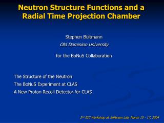
The STAR Time Projection Chamber
The STAR Time Projection Chamber. Fabrice Reti è re (LBNL) for the STAR collaboration. TPC function Large acceptance gas detector | h |<1.8 Full azimuthal coverage Momentum reconstruction Tracking with design hit position resolution ~500 m m Pid using dE/dx Design resolution : 7%.

The STAR Time Projection Chamber
E N D
Presentation Transcript
The STAR Time Projection Chamber Fabrice Retière (LBNL) for the STAR collaboration
TPC function Large acceptance gas detector |h|<1.8 Full azimuthal coverage Momentum reconstruction Tracking with design hit position resolution ~500 mm Pid using dE/dx Design resolution : 7% TPC design Tuning the TPC Position reconstruction Drift velocity Drift distortion dE/dx Understanding ionization Gain calibration Introduction
0.5 Tesla magnet 0.25 for year 1 Trigger CTB ZDC Level 3 Year 1 detectors TPC RICH 1 SVT ladder STAR detector
Gas : P10 (Ar-CH4 90%-10%) @ 1 atm Drift voltage : -31 kV TPC gas volume
Pad readout • 2×12 super-sectors 190 cm Outer sector 6.2 × 19.5 mm2 pad 3940 pads Inner sector 2.85 × 11.5 mm2 pad 1750 pads 127 cm 60 cm
FEE, custom design IC : SAS + SCA (512 time bins) Readout 140K channels, i.e. 70M pixels Readout board Carry ~1000 Channels to DAQ TPC Pad Shaper Amp Analog Memory Preamp ADC ADC SCA SCA Fiber optic transmitter to DAQ X 16 M U X SCA + ADC IC SAS IC FEE Board Readout Board Electronic readout
TPC at workFirst RHIC events Detector very stable Good for physics without calibration
TPC at work dE/dx measurement before calibration dEdx resolution good for Pid d p K e
Ionization Pid using dE/dx Electron drift Drift distortion Drift velocity (laser) Gain Gas gain Electronic gain Tuning the TPCProcesses to control Particle
Laser for coarse value Fine adjustment from tracking matching both side of the TPC Electron driftDrift velocity under control 5.45 Drift velocity (cm/ms) 5.44 1020 1010 Alexei Lebedev, Bill Love, Jeff Porter (BNL) Pressure (mbar)
Distortion sources Radial B field (<2mm) End cap location (800 mm) E field corrections to field cage (400 mm) 0.5 mrad E/B field misalignment (400 mm) Detected using residual average over many tracks Corrections using field maps and geometry survey No tuning on data required Electron driftDrift correction in TPC 0.3 0. Average residual (mm) -0.3 60. 100. 140. Radius (cm)
Electron driftB field map correction Measured Br/Bz Calculated distortion = ExBr 1. Br/Bz (%) Radius (cm) Radius (cm) 0.4 140 140 R/f distortion (mm) 0 0. 100 100 TPC active volume TPC active volume -0.4 60 60 -1. -0.8 20 20 -200 -100 0 200 -200 -100 0 100 200 100 Distance to central membrane (cm) Distance to central membrane (cm) Field map allows parameter free calculation Bill Love, Al Saulys (BNL), Jim Thomas (LBNL)
No wires at the boundary between inner and outer sector E field leak E field radial component ExB effect on R/f Electron driftInner/outer sector boundary 0.2 Inner sector Data 0.1 Outer sector Average residual (mm) 0. -0.1 10 20 30 Pad row # 1.6 cm Gating grid = -127 V Calculation Ground plane = 0 V Average residual (mm) gap Inner sector Outer sector Outer sector Inner sector Radius (cm)
Electron driftdistortions under control Average residual All calculated distortions 1. Radius (cm) 0.2 R/f distortion (mm) 140 0 Inner sector Outer sector 100 Average residual (mm) -1. TPC active volume 0. 60 20 -0.1 -2. -200 -100 0 100 200 10 20 30 Pad row # Distance to central membrane (cm) Huan Huang, Hui Long and Steve Trentelange (UCLA) Jim Thomas (LBNL)
Gain variation Over TPC sectors With time Pressure Temperature … Correction using average dEdx Require a lot of events to cancel out fluctuations Gain monitor chamber being built Pulser for electronic gain calibration Gain uniformityGas gain 1.6 Gain (arb. unit.) 1.5 1.4 1.3 1000 1010 1020 1030 Pressure (mbar) Eugene Yamamoto (UCLA)
To measure uniformity of electronic gain 8% sigma variation but 20% RMS (tail) Precise channel level correction Pulser also identifies dead channels = 0.25% Ground plane Gating grid Pad plane Anode TPC drift volume Pulser Gain uniformityElectronic gain Pulser amplitude (arb. unit.) Outer sector Inner sector
Ionization and gain uniformity dEdx resolution sdE/dx/(dE/dx) (%) Remaining issue : correlation of dE/dx between pad rows Track length (cm) Yuri Fisyak (BNL)
Conclusion particle identification 12 p d dE/dx (keV/cm) 8 K 4 m e 0 Aihong Tang (Kent State U)
Approaching design performance Good particle separation using dE/dx 7.5% p-proton separation : 1.3 GeV/c Position resolution 500 mm 2-Track resolution 2.5 cm Momentum resolution 2% Future challenges Achieve turn-key operation Handle increased luminosity Lots of physics from the year 1 data Collective flow Identified particle spectra Particle correlations Event by event physics Strangeness … The TPC is an excellent tool for physics

![The Bloody Chamber [The Bloody Chamber Week]](https://cdn1.slideserve.com/2357523/the-bloody-chamber-the-bloody-chamber-week-dt.jpg)