Download
1 / 21
210 likes | 369 Vues
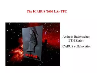
The ICARUS T600 Liquid Argon Time Projection Chamber. Francesco Arneodo Laboratori Nazionali del Gran Sasso on behalf of the ICARUS Collaboration. The ICARUS Collaboration.

E N D
The ICARUS T600 Liquid Argon Time Projection Chamber Francesco Arneodo Laboratori Nazionali del Gran Sasso on behalf of the ICARUS Collaboration F. Arneodo Imaging 2003
The ICARUS Collaboration S. Amoruso, P. Aprili, F. Arneodo, B. Babussinov, B. Badelek, A. Badertscher, M. Baldo-Ceolin, G. Battistoni, B. Bekman, P. Benetti, A. Borio di Tigliole, M. Bischofberger, R. Brunetti, R. Bruzzese, A. Bueno, E. Calligarich, D. Cavalli, F. Cavanna, F. Carbonara, P. Cennini, S. Centro, A. Cesana, C. Chen, Y. Chen, D. Cline, P. Crivelli, A.G. Cocco, A. Dabrowska, Z. Dai, M. Daszkiewicz, A. Di Cicco, R. Dolfini, A. Ereditato, M. Felcini, A. Ferrari, F. Ferri, G. Fiorillo, S. Galli, Y. Ge, D. Gibin, A. Gigli Berzolari, I. Gil-Botella, A. Guglielmi, K. Graczyk, L. Grandi, X. He, J. Holeczek, C. Juszczak, D. Kielczewska, J. Kisiel, L. Knecht, T. Kozlowski, H. Kuna-Ciskal, M. Laffranchi, J. Lagoda, B. Lisowski, F. Lu, G. Mangano, G. Mannocchi, M. Markiewicz, F. Mauri, C. Matthey, G. Meng, M. Messina, C. Montanari, S. Muraro, G. Natterer, S. Navas-Concha, M. Nicoletto, S. Otwinowski, Q. Ouyang, O. Palamara, D. Pascoli, L. Periale, G. Piano Mortari, A. Piazzoli, P. Picchi, F. Pietropaolo, W. Polchlopek, T. Rancati, A. Rappoldi, G.L. Raselli, J. Rico, E. Rondio, M. Rossella, A. Rubbia, C. Rubbia, P. Sala, R. Santorelli, D. Scannicchio, E. Segreto, Y. Seo, F. Sergiampietri, J. Sobczyk, N. Spinelli, J. Stepaniak, M. Stodulski, M. Szarska, M. Szeptycka, M. Terrani, R. Velotta, S. Ventura, C. Vignoli, H. Wang, X. Wang, M. Wojcik, X. Yang, A. Zalewska, J. Zalipska, P. Zhao, W. Zipper. ITALY: L'Aquila, LNF, LNGS, Milano, Napoli, Padova, Pavia, Pisa, CNR Torino, Politec. Milano. SWITZERLAND: ETHZ Zürich. CHINA: Academia Sinica Beijing. POLAND: Univ. of Silesia Katowice, Univ. of Mining and Metallurgy Krakow, Inst. of Nucl. Phys. Krakow, Jagellonian Univ. Krakow, Univ. of Technology Krakow, A.Soltan Inst. for Nucl. Studies Warszawa, Warsaw Univ., Wroclaw Univ. USA: UCLA Los Angeles. SPAIN: Univ. of Granada. F. Arneodo Imaging 2003
Outline • The LAr TPC Technology • The T600 Detector • Results from the 2001 run in Pavia F. Arneodo Imaging 2003
The technique - I Operating principles of the ICARUS LAr TPC: • ionizing events taking place in a volume of LAr (where a uniform electric field is applied) produce electron-ion pairs • These charges drift along the field lines. The motion of the much faster electrons induces a current on the anode. The electrons can drift several metres if the LAr is highl purified(electronegative impurities < 0.1 ppb O2 equiv.) F. Arneodo Imaging 2003
The LAr TPC Technology (2) Non-destructive multiple readout Raw Data from a 10 m3 prototype Scintillation Light Signals induced Time -- drift e- Charge C Ionizing track 1st Induction wire/screen grid A B Drift time 2nd Induction wire grid (x view) d Charge C d Collection wire grid (y view) p B Drift time A 400 ns sampling Continuous waveform recording F. Arneodo Imaging 2003
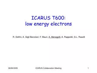
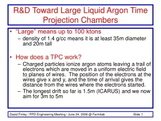
The LAr TPC Technology (3) • No charge multiplication occurs in LAr • LAr is also a very good scintillatorscintillation light (l = 128 nm) provides a prompt signal to be used for triggering purposes and for absolute event time measurement • High electron mobility (~500 cm2V-1s-1) • Possibility of extreme purification (<0.1 ppb O2) • Long electron life time (>ms) and drift paths (>m) • High electron-ion pairs yield (~ 10000 e- for 2 mm of a m.i.p. track) density: 1.4 g/cm3dE/dx: 2 MeV/c • Available in large quantities (GAr ~ 0.9% of air) F. Arneodo Imaging 2003
The T600 Module • Two separate containers • inner volume/cont. = 3.6 x 3.9 x 19.6 m3 • Sensitive mass = 476 t • 4 wire chambers with 3 readout planes at 0°, ±60° (two chambers / container) • ≈ 54000 wires (chann.) • Maximum drift = 1.5 m • HV = -75 kV @ 0.5 kV/cm • Scintillation light readout with 8” VUV sensitive PMTs F. Arneodo Imaging 2003
LAr Cryostat (half-module) The T600 Module during construction View of the inner detector 4 m 4 m 20 m F. Arneodo Imaging 2003
The T600 Module • Approved and funded in 1996 • Built between years 1997 and 2001 • Completely assembled in the INFN assembly hall in Pavia • Demonstration test run during first half 2001 • Three months duration • Completely successful • Data taking with cosmic rays • Installation plan in the Gran Sasso underground Lab completed early 2003 • Transportation and installation in LNGS in 2003-2004 F. Arneodo Imaging 2003
Lifetime evolution during T600 Pavia run F. Arneodo Imaging 2003
T600 Data 6 m Muon bundle event (Run 699, Event 48) F. Arneodo Imaging 2003
3-D reconstruction F. Arneodo Imaging 2003
e.m + hadron shower 2.2 m F. Arneodo Imaging 2003
Long longitudinal muon track crossing the cathode plane 18 m Right Chamber 1.5 m Cathode Left Chamber 1.5 m Track Length = 18.2 m dE/dx = 2.1 MeV/cm 3D View Top View 3-D reconstruction of the long track F. Arneodo Imaging 2003 dE/dx distribution along the track
3d reconstruction of a single muon F. Arneodo Imaging 2003
Air Shower run 834 ev. 6 right chamber collection view left chamber collection view F. Arneodo Imaging 2003
Run 939 Event 95 Right chamber Te=36.2 MeV Range=15.4 cm Stopping muon reconstruction example Induction 1 view A µ+ B e+ Induction 2 view C A µ+ B e+ Collection view C F. Arneodo Imaging 2003
1.8 MeV 3.2 MeV 10 MeV Two consecutive wires d-rays T600 Data F. Arneodo Imaging 2003
In-flight annihilation of positron ≈20% of positrons from µ decays expected to annihilate before stopping Run 844, Event 24 e+e- pair e+ + Collection view Induction 2 view annihilation point F. Arneodo Imaging 2003
Physics goals • atmospheric and long baseline n studies • proton decay F. Arneodo Imaging 2003
Work is going on: • Installation at Gran Sasso: tenders, infrastructures, etc. • Optimization of electronics and trigger • Analysis (calorimetry, m momentum with multiple scattering, muon bundles, scintillation and Cherenkov light) F. Arneodo Imaging 2003