High-Precision Kinematic Couplings for Robotic Interfaces
This technical report explores the design and testing of high-accuracy, repeatable wrist interfaces and modular baseplates for robotic applications. It focuses on various kinematic coupling methods, emphasizing the importance of managing Hertz contact stresses for optimal performance. Prototype designs, including canoe balls and three-pin interfaces, are presented alongside extensive repeatability testing data collected at ABB Robotics. The report outlines the essential steps for improving coupling configurations and enhancing production feasibility for real-world applications.

High-Precision Kinematic Couplings for Robotic Interfaces
E N D
Presentation Transcript
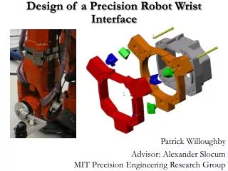
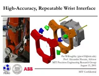
High-Accuracy, Repeatable Wrist Interface Pat Willoughby (pjwst10@mit.edu)Prof. Alexander Slocum, AdvisorMIT Precision Engineering Research GroupAugust 15, 2001
Overview of Common Coupling Methods Flexural Kin. Couplings Kinematic Constraint Pinned Joints No Unique Position Elastic Averaging Non-Deterministic Kinematic Couplings Kinematic Constraint Quasi-Kinematic Couplings Near Kinematic Constraint
Exact Constraint (Kinematic) Design • Exact constraint means a component has an equal number of constrained points to number of degrees of freedom • If component is over constrained, clearance and high tolerances required to prevent premature failure or assembly incompatibility • Kinematic design means that the motion is exactly constrained and geometric equations can be written to describe its motion • Kinematic Couplings constrain components exactly, commonly providing repeatability of ¼ micron or on the order of parts’ surface finish • Managing Hertz contact stresses is the key to successful kinematic coupling design
Schematic of Three Pin Coupling Design Preload Bolt and Third Pin Two “Pins” on Arm Plate Two “Holes” On Wrist Plate
Prototype Wrist Plate Mounting Tests at ABB Robotics Vasteras, July/August 2001: • Test static (bolted) and dynamic (5-point path) repeatability of canoe ball and three-pin wrist prototypes • Test variety of preloads (canoe balls) • Replacement in two orientations (45 and 90 degrees to ground) • Measure tool point motion using Leica LTD500 Laser Tracker • Repeatability of robot path + measurement system approximately 20 microns
Repeatability Performance • Canoe balls vs. Normal Wrist @ 45 deg = 35% reduction • Canoe balls vs. Normal Wrist @ 90 deg = 64% reduction • Three-pin vs. Normal Wrist @ 45 deg = 44% reduction
Recommended Next Steps • Test three pin coupling in lab setting for ideal case repeatability • Adapt canoe ball design to fit into space of wrist • Suggest production designs for different concepts • Investigate: • Three pin coupling in 90 degree position • Effect of friction reduction using TiN coated elements or lubrication • Coupling design independent of mounting position • Applicability quasi-kinematic couplings • Evaluate long-term dynamic performance
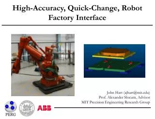
High-Accuracy, Quick-Change, Robot Factory Interface John Hart (ajhart@mit.edu)Prof. Alexander Slocum, AdvisorMIT Precision Engineering Research GroupAugust 15, 2001
Project Goals Design, test, and demonstrate production feasibility of a modular robot baseplate with kinematic couplings as locators: • A repeatable, rapidly exchangeable interface between the foot (three balls/contactors) and floor plate (three grooves/targets) • Calibrate robots at ABB to a master baseplate • Install production baseplates at the customer site and calibrated the kinematic couplings directly to in-cell tooling • Install robot according to refined mounting process with gradual, patterned preload to mounting bolts • TCP-to-tooling relationship is a deterministic frame transformation • Base calibration data handling is merged with ABB software, enabling 0.1 mm TCP error contribution from repeatability and exchangeability error of kinematic couplings
Prototype Coupling Designs Design 3-point kinematic coupling mounts for the 6400R foot: Canoe Ball • Six “point” contacts • 0.5 m radius ball surface • 20 mm diameter elastic Hertzian contact Three-Pin • Three line + three surface contacts • In-plane preload overcomes friction to deterministically seat pins • Vertical bolt preload engages horizontal contact surfaces
Prototype Coupling Designs Groove/Cylinder • Twelve line contacts • Aluminum cylinders • Apply bolt preload (elastic deflection of cylinders) for dynamic stability
Prototype Base Mounting Tests at ABB Robotics Vasteras, July/August 2001: • Static (bolted) and dynamic (5-point path) repeatability of canoe ball and three-pin interfaces • Static (manipulator rest only) repeatability of groove/cylinder interface • Test both basic (air wrench) and refined (torque wrench, greased bolts) mounting processes • Measure tool point motion using Leica LTD500 Laser Tracker • Repeatability of robot path + measurement system approximately 20 microns
Repeatability Performance • Three-pin vs. BMW base = 83% reduction • Canoe balls vs. BMW base = 85% reduction • Cylinders vs. BMW base = 92% reduction • Refined mounting vs. basic mounting = 50-70% reduction • 8-bolt blue pallet repeatability (not shown) = 1.63 mm
Exchangeability Performance Simulate exchangeability error from manufacturing variation: • Calibrate interfaces by measuring contacts and calculating interface error transformation • Model direct measurement of pins + contacts, and offset measurement of canoe balls • Exchangeability is error between calculated and true interface transformation, given chosen level of calibration and manufacturing tolerances (low, med, high) • 250-trial Monte Carlo simulation in MATLAB at each calibration level Three-pin exchangeability: 0 = no interface calibration 3 = full (x,y,z) of pins and contact surfaces
Total Mechanical Accuracy “Quick-Change” Accuracy = Repeatability + Exchangeability (measured) (simulated) Canoe balls Three-pin Groove/cylinder 0.22 mm = 0.06 + 0.16* 0.12 mm = 0.07 + 0.05 - = 0.03** + (Incomplete) • Interface calibration decouples accuracy from manufacturing tolerances of mounting plates and couplings (if direct measurement of contacts) • Results show repeatability is highly f(mounting process) – this may present a performance limit for factory mountings; interface should be micron-repeatable under perfect conditions • Totally, a near-deterministic prediction of robot interface accuracy *driven by error of offset position measurement **static only
Recommended Next Steps • Test groove/cylinder interface with preload + motion • Test traditional quasi-kinematic couplings • Evaluate long-term dynamic performance • Design production three-pin adaptation to BMW 2-pin base • Evaluate canoe ball 4-point mounting for Voyager? • Build kinematic coupling “Expert System” – combine test results, simulation results, etc. into design tool that gives minimum cost design recommendation and tolerance budget as f(accuracy requirement)