A Standard actuator
Control algorithm (Open-loop or closed loop) Condition monitoring Fault detection and isolation. 1. Control algorithm (Open-loop or closed-loop. Paradigm shift. A Standard actuator. A Standard actuator. 1. Microelectronics 2. Digital system 3. Distributed control

A Standard actuator
E N D
Presentation Transcript
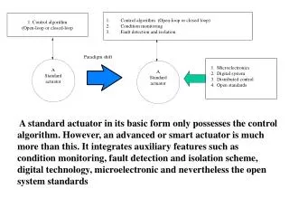
Control algorithm (Open-loop or closed loop) • Condition monitoring • Fault detection and isolation 1. Control algorithm (Open-loop or closed-loop Paradigm shift A Standard actuator A Standard actuator 1. Microelectronics 2. Digital system 3. Distributed control 4. Open standards A standard actuator in its basic form only possesses the control algorithm. However, an advanced or smart actuator is much more than this. It integrates auxiliary features such as condition monitoring, fault detection and isolation scheme, digital technology, microelectronic and nevertheless the open system standards
Performance can be improved by monitoring the condition of the actuators on-line. Condition monitoring attempts to identify faults. Motors can be monitored by the use of physical parameters, such as voltage, current, speed, magnetic flux, armature resistance/inductance, magnetic flux, viscous friction, dry friction etc.
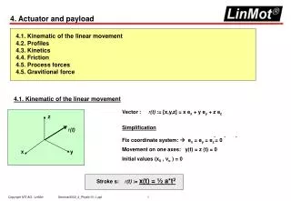
Pneumatic actuators have been used for servo applications even as axes of numeric control machine systems. The motion sequence of a Numerically-Controlled (NC) axis in a packaging system in which bottles are to be inserted into a container consists of various positions to which the NC axis moves. Figure illustrates a typical application in a packaging system.
Principal elements of a typical pneumatic actuator system The actuator is interfaced with three major elements; controller, feedback sensors and a valve.
MOTOR Position Controller Speed Controller Power Controller + + - - Torque Current Speed Position + - Figure shows the basic feedback system configuration of a servo motor control system. It is seen that the basic concepts of motor control systems falls under three categories, namely; torque control, speed control and position control. The position and speed information are usually obtained from the encoder. The current information is obtained from the current sensors.
End effector CAMERA Joints (Actuator) Arm Controller Infrared sensor Interface Vehicle Body Controller End effector B A S E Wheels An industrial robot is a re-programmable, multifunctional manipulator designed to move materials, parts, tools or special devices through variable programmed motions for performing a variety of tasks. There are various types of robots in the practical field of application. One of the classifications is based on whether they are fixed or mobile.
Source of Information Source of Energy Process Source of Information Source of Energy Control Element Measurement Devices (sensors) Robot Robot CPU Operational Unit Computer Controller Workspace Workspace The central processing unit is concerned with data processing. The operational unit is the physical robot itself. It takes action on the workspace by using, transforming and/or acquiring energy from the suitable source(s) and reacting to the signals and commands are provided by the sensory systems and central processing unit.
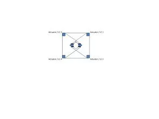
Mobile robots sometimes called Autonomous Guided Vehicle (AGVs) are currently used for transporting material in industry, warehouses and underground mining and are also developed for exploration of the oceans and space, etc. AGV architectural view in the control context is shown in this slide
The control system in the AGV is essentially distributed according to the physical location of the devices and control software. That is the complete vehicle is based on a distributed control design concept. The figure illustrates the schematic diagram of components in a DCS conformant AGV control architecture.
A three-axis platform for drilling the PCB board was chosen for giving an example of another mechatronic system. The platform has three axes; x, y and z. Z-axis holds the needle to drill holes on the PCB board. The PCB boards are passed to the workbench through a conveyor system driven by an AC motor. When the PCB board reaches at the right position called station the gripper rigidly holds the board so that the z-axis of the platform will be able to do its job properly i.e., doing drilling operation without any shaking.
The control system for three-axis platform has a generic set of essential requirements in terms of co-ordination, synchronization, acknowledgement, timing etc. A DCS network with five nodes has been designed for the operation of the drilling machine.
The material handling is the movement, protection, storage of materials and products throughout the process of their manufacture, assembly and distribution. The above figure illustrates the control flow chart of a typical conveyor based material handling system.
PC with PCI Network DELIVER Y card (inside) Windows98 IF temp >= T LCA Object Server (LNS) and CV >= cv% NetBuild, NetInstall, NetMonitor stop motor Visual Basic (control loop) LonWorks Network Robot Controller Packing Box N2 N1 N3 interfacing circuits Interfacing interfacing circuits interfacing circuits temperature switches sensor smart Motor colour sensor pick and place robot switch objects Supply Side PRODUCTION CELL PRODUCTION LINE CONVEYOR SYSTEM Figure shows the schematic diagram of this conveyor-based material handling system and control. It includes conveyor belt, Pick-and-Place robotic workstation, control components such as, a single phase AC motor, a temperature sensor, two microswitches an a colour sensor. The demonstration application involves the loading of product from the conveyor into defined containers.
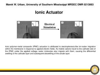
A device is considered intelligent if it has the capability of producing some sort of validation pointer. An illustration of validated inspection.
Fusion technique-based colour sensor validation When identical devices at least triplex in configurations are verified by comparing the measured value at a given instant and the failure/validation modes are isolated by majority voting it is then referred to as fusion technique.
A typical but simple validation implementation with regard to electric motor type actuator, used for driving conveyor based material handling system.
Some interfacing circuits for color sensor used in the Conveyor-based material handing system.
Some interfacing circuits for color sensor used in the Conveyor-based material handing system.
Some interfacing circuits for RTX robot. The interfacing between the RTX controller (PC) and LON system was achieved through USB (A game port is a port that is incorporated into a computer conventionally using a 15-pin D-style connector) of the PC
Interface circuit for motor node is illustrated in the figure. The motor can be started and emergency stopped manually by pressing the manual buttons. The motion can also be reversed when required.
The circuit diagram of the Relay Box can be seen in this figure. The relays are equipped with diodes in order to prevent high-voltage spikes in the Relay Box terminals, which cloud destroy the LON nodes connected to it.