Download
1 / 37
370 likes | 490 Vues
Discover various Localization Methods discussed in a presentation by Jeremy Elson to CS694 in 1999, including absolute and relative localization techniques like proximity-to-reference, angles-to-reference, and signal fading. Get insights into topological localization, VOR, GPS, and more.

E N D
A SurveyofLocalization Methods Presented to CS694 November 19, 1999 Jeremy Elson
what’s the problem? • WHERE AM I? • But what does this mean, really? • Frame of reference is important • Local/Relative: Where am I vs. where I was? • Global/Absolute: Where am I relative to the world? • Location can be specified in two ways • Geometric: Distances and angles • Topological: Connections among landmarks
localization: relative • If you know your speed and direction, you can calculate where you are relative to where you were (integrate). • Speed and direction might, themselves, be absolute (compass, speedometer), or integrated (gyroscope, accelerometer) • Relative measurements are usually more accurate in the short term -- but suffer from accumulated error in the long term • Most robotics work seems to focus on this. This talk will focus on absolute localization.
localization: absolute • Proximity-To-Reference • Landmarks/Beacons: ParcTab, Active Badges • Angle-To-Reference • Visual: manual triangulation from physical points • Radio: VOR • Distance-From-Reference • Time of Flight • RF: GPS, PinPoint • Acoustic: Active Bat, Lew • Signal Fading • EM: Bird/3Space Tracker • RF: SCADDS/SCOWR, Niru • Acoustic: Jer?
topological maps • Really the most “natural”: how did you get to class today? • You have a map of known landmarks and the connections among them • You even convert metric maps to topological! • Probably the most useful for location-aware computing • “Closest printer” really means the one in this room, not on the other side of a wall
topological localization • ParcTab and Active Badges • Infrared transmission picked up by recivers in all rooms • Works precisely because infrared propagation matches topological boundaries of environment • Reverse is also possible: landmarks • SCADDS localization beacons • Problems: difficult to control granularity; apps may need geometric map
triangulation Land Landmarks Works great -- as long as there are reference points! Lines of Sight Unique Target Sea
compass triangulation cutting-edge 12th century technology Land Landmarks Lines of Sight North Unique Target Sea
celestial navigation • Same idea, except in 1D, and reference point is a star • Angle of between north star and horizon determines latitude • Works only because north star is close to axis of Earth’s rotation • Longitude is much harder • Note: Points to non-flatness of earth Encyclopedia Britannica
VOR: modern triangulation • VOR is an aircraft navigation system still widely prevalent today • Same concept as visual landmarks, except that radio beacons emit directional signals • Aircraft can determine (within 1o) their bearing to a VOR station • 1 VOR fix will tell you bearing-to-target; 2 tells you absolute position http://www.interlog.com/~bitewise/aviation/navplan/radionav.htm
vor for localization 2 VORs plus a map will uniquely determine 2-D position
VOR’s magic • VOR stations transmit two signals: • An omnidirectional reference signal, with a 30 Hz amplitude modulation • A highly directional continuous signal that sweeps through 360 degrees at 30Hz • Result: aircraft sees two sine waves: reference modulated by transmitter, azimuth signal modulated by directionality • Receiver computes phase shift between them to get bearing
distance-to-reference systems • Measure distance from ref point to target • For n dimensions, n measurements give you 2 sol’ns; n+1 is unique • Domain knowledge can often be used instead of n+1’th measurement
accuracy constraints • Accuracy depends on: • Precision of the distance measurements (represented below as thickness of the circles) • Geometric configuration of the reference points Reference points far apart: small overlapping region Reference points close together: large overlapping region
measuring distance • Measure time-of-flight • Biggest problem: time synchronization • Time sync and localization are often intertwined • If only Einstein was wrong, and information could travel instantaneously... • GPS, PinPoint, Active Bat all deal with the time problem in different ways • Measure signal strength • Used less often because relationship between strength and distance is harder to model (also not linear)
gps: global positioning system • 24 satellites launched by U.S. DOD, originally for weapons systems targeting • Gives time & position anywhere in the world, although often only outdoors • Typical Position Accuracy: • Civilian: Horiz 50m, Vert 78m, 3D 93m, 200ns • Diff: Horiz 1.3m, Vert 2.0m, 3D 2.8m, 350ns • Military accuracy might be usable in 2000 http://tycho.usno.navy.mil/gpsinfo.html http://www.trimble.com/gps/howgps/gpsfram2.htm
the basic idea • Satellites constantly transmit beacons along with the time-of-beacon and position (in predictable, corrected, and observed orbits) • Receivers listen for (phase-shifted) signals and compute distance based on propagation delay (assume magically synced clocks for now) • 3 satellites gives you 2 points (in 3d); throw out the one in deep space • Compute position relative to satellites; use satellite position to get Earth coordinates
effects of clock bias true distance biased distance
solving for clock bias • Critical point: satellites are perfectly synchronized (using expensive atomic clocks synchronized before launch) • If all signals are received simultaneously, they are all off by a constant bias • This means that by adding an additional satellite, we can solve for clock bias. (Would not work if off by a constant factor) • This gives us both position and time!
solving for clock bias true distance biased distance
sources of gps errorper satellite • Satellite clock drift (1.5 m) (1usec = 300m) • Orbit estimation errors (2.5 m) • Atmospheric and relativistic effects (5.5 m) • Receiver noise (0.3 m) • Multipath interference (0.6 m) • Intentional randomization to reduce civilian grade accuracy (30m) http://www.trimble.com/gps/howgps/gpsfram2.htm
differential gps • A way of getting more accurate GPS data • Receivers at known positions find the difference between computed & true position • Computed error correction factor transmitted to other GPS receivers in the area • Corrects for all errors that the receiver has in common with the reference (atmospheric, relativistic, orbital, sat clock, randomization)
pinpoint 3d-id • Local positioning system by Pinpoint Co. • Meant to track large numbers tags indoors • Tags should be cheap and all have IDs • Infrastructure knows where tags are; tags don’t know anything • Compare to GPS: Infrastructure knows nothing, tags know where they are • ~1-3 m accuracy http://www.pinpointco.com/_private/whitepaper/rfid.html
the clock problem • Their solution: • Interrogator transmits a test signal • Tag simply changes the signal’s frequency and transponds it back to the interrogator (with tag ID modulated in) • Interrogator receives transponded signal • Subtracting out fixed system delays yields time of flight • They avoid the clock sync problem by making the transmitter and receiver the same device
implementation details • Area to be monitored is divided up into “cells” - each with antennas & controller • Coarse-grained location first (which cell?), then fine-grained location within the cell • Query driven: “Tag 5 raise your hand!”, or • Tag driven: all tags periodically beacon (impl.) • Tag beaconing frequency might depend on inertial system • Collision reduction through various techniques, including reducing beacon time • They note non-linear increase in perf due to this
active bats • Research project at ORL-cum-AT&T • Similar goals as Pinpoint: indoor LPS 100mm x 60mm x 20mm http://www.uk.research.att.com/bat/
bats at work • Tags have unique IDs, radio receivers and ultrasound transducers • Interrogator consists of a radio transmitter and “microphones” (ultrasound detectors) • Interrogator sends radio message: “Tag 5, signal now!” • Tag 5 receives the radio message and sends an ultrasonic pulse • Microphones pick up the sound; time of flight calculated
the clock problem • Use two modalities: RF for control (very fast), sound for measurement (slow) • We can simulate instantaneous info flow because it is almost instant relative to what we’re measuring • Speed of sound: 344 m/s • Speed of light: 300M m/s (30m = 0.1 usec) • 0.1 usec * 344m/s = 0.000 034 4 m • Like Pinpoint, subtract out fixed delays (empirically derived) to get flight time
implementation details • Multiple peaks may be detected (echoes - audio version of multipath interference) • Two heuristics for eliminating echos: • Difference in distance between two measurements can’t be larger than the distance between the two microphones. • If so, larger one must be a reflection • Do statistical tests to identify outliers; repeat until variance is low or only 3 points remain • Nice extension: use 3 tags to detect 3d pose as well as position of objects
active bat accuracy 95% within 14cm for raw measurments 95% within 8cm when averaged over 10 samples ftp://ftp.uk.research.att.com/pub/docs/att/tr.97.10.pdf
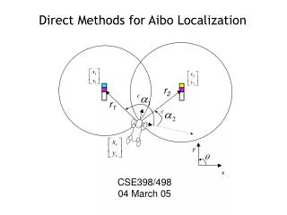
active lew-bats • Goal: distance between two robots • One robot simultaneously: • Sends a message over the network to the target robot • Emits an audio chirp from the sound card • Target robot: • Waits for network message • Listens for chirp, calculates time of flight • Evaluation in progress
distance measurement:using signal fading • Another class of localization systems uses reduction in the strength of a field to measure distance • Magnetic Field: Ascension “Flock of Birds”, Polaris 3space tracker • RF: No (??) commercial products; work here on SCADDS/SCOWR • Sound: A half baked idea of mine
flock of birds • Measures 3D position and orientation • Consists of largish transmitter & small receiver connected to the same controller • Receiver picks up orthogonal magnetic fields from transmitter (details unknown) • Specs claim 0.02”/0.1o precision over 10’ area • Not really that good; and metal screws it up • Magnetic field falls off as r4 (?) • Mostly head tracking apps & similar http://www.ascension-tech.com/products/flockofbirds
radio signal strength • Work going on here (SCADDS, SCOWR: Nirupama Bulusu, Puneet Goel) • Can radio signal strength be used as a reliable distance measurement? • Very difficult to model indoor radio prop. • Current test implementation • Radiometrix RPC radio transmitter • RxM receiver module with RSSI output pin
an initial test Signal Strength Indicator Distance in Meters Nirupama Bulusu and Puneet Goel
sound off • Half baked idea: can we measure falloff in audio volume as a distance estimate? • ...I told you it was half baked, that’s all I have to say about that :)
that’s all, folks! And, remember: wherever you go, there you are.