Direct Geometry Processing for Tele-Fabrication: Innovations in 3D Manufacturing
This paper discusses cutting-edge advancements in tele-fabrication, focusing on direct geometry processing for 3D data acquisition. It addresses the techniques involved in point cloud slicing, support generation, and mask image planning essential for efficient fabrication. By integrating advanced scanning and printing technologies, it presents a method to enhance the design and manufacturing processes. The findings from physical experiments verify the effectiveness of these techniques, paving the way for future improvements in 3D tele-fabrication systems.

Direct Geometry Processing for Tele-Fabrication: Innovations in 3D Manufacturing
E N D
Presentation Transcript
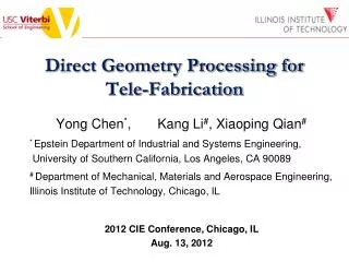
Direct Geometry Processing for Tele-Fabrication Yong Chen*, Kang Li#, Xiaoping Qian# * Epstein Department of Industrial and Systems Engineering, University of Southern California, Los Angeles, CA 90089 # Department of Mechanical, Materials and Aerospace Engineering, Illinois Institute of Technology, Chicago, IL 2012 CIE Conference, Chicago, IL Aug. 13, 2012
CONTENTS • Introduction of 3D tele-fabrication • 3D data acquisition • Geometry processing • Point cloud slicing • Support generation • Mask image planning • Fabrication results and discussion • Summary 2
2D Faxing Printing (Los Angeles) 2D Scanning (Chicago) 3
3D Scanners • Zcorp • Makebot 3D replicator • NextEngine • 3Shape • HDI 3D Scanner • etc.
3D Printers • Cubify • VFlash • Perfactory • ZCorp • Objet • Projet • uPrint • etc.
3D Faxing Geometry processing Points • An open question: how should geometry be processed in future 3D faxing systems? Polygonal meshes (STL) ? 3D Scanners 3D Printers
3D Tele-fabrication overview Point cloud slicing Support generation Mask image planning Geometry processing Manufacturing (Los Angeles) 3D Scanning (Chicago) 8
Geometry processing flowchart Physical object Scanned point data Sliced contours Support structure Manufactured model Chicago Los Angeles 9
Data acquisition Computer 3D digitizer Object Rotary stage Digitizing system 6-step range image scanning 10
Point cloud slicing overview Point cloud Morse function and MLS surface Critical points and Morse-Smale complex Sliced model Enhanced Reeb graph 11
Moving Least Square (MLS) surface Implicit definitionstationary set of a projection operator Energy function Energy function and normal vector field Normal vector field MLS explicit definition MLS surface point with local minimum energy 12
Critical points • Critical points identified by: • Slicing contour topology controlled by critical points Morse function f: height value 4 types of critical points Contour topology φon MLS 13
Morse-Smale complex and enhanced Reeb graph Grouping / Pruning MS complex: integral lines tracing Enhanced Reeb graph: MS complex re-organizing • Morse-Smale (MS) complex: tracing integral lines from saddles to maximum/minimum • Enhanced Reeb graph: graph processing of MS complex 14
Enhanced Reeb graph as contour marching start Sliced model: all raised contours stacked Slicing plane Intersection with enhanced Reeb graph Contour marching from intersected point 15
Curvature-adaptive contour marching Contour marching by intersection Curvature-adaptive step size Point subset near the slicing plane Adaptive contour points generation • Step size determined by osculating radius 16
Support generation based on contours • Supports are required to ensure the success of the 3D printing process • No drifting/floating away; • Reduce deformation due to shrinkage. 17
Contour-based support generation principle Two consecutive layer contours Support structure analysis 18
Support generation algorithms C = A ∩ B 1 A B 4 Sanchor = B - Sself B r 2 D = C offset by r A A 3 Sself = D ∩ B Current layer B Previous layer A Sanchor: anchor-support region Sself: self-support region 19
Anchor-support region covering B A B A CAD model of supports (Contours based) Support layout by region covering CAD model of support by Lightyearsystem (STL based) Input regions 20
Support generation examples Sliced model Point cloud Support structure 21
Mask image planning: Image projection of layers Mask image of part Mask image of support Projection mask image 22
Fabrication example (1) (2) Point cloud Sliced model Fabricated model 23
Manufacturing compatibility with different layer thickness Macro- Meso- Micro- 24
Summary • Tele-fabrication is critical for future product design and manufacturing • Developed a tele-fabricating approach by integrating 3D scanning and printing • Presented a direct geometry data flow method in such an integration system • Performed physical experiments to verify the effectiveness of the direct geometry method. 25
Acknowledgments • National Science Foundation CMMI-0927397 (USC). • National Science Foundation CMMI-0900597 and CMMI-1030347 (IIT) 26
Questions? 27