Download

1 / 73
730 likes | 778 Vues
Explore the evolution of traffic signal controllers from electro-mechanical to NEMA TS-2 systems. Learn their basic operation, detection methods, and battery backups. Discover key components, cabinets, and controllers. Suitable for traffic engineers and technicians.

E N D
MOVITE 2012Traffic Signal Workshop • History / Basic Operation • Detection • Battery Back Up’s • Fiber Communications • Inspections
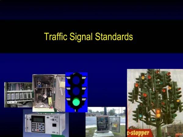
ELECTRO – MECHANICAL • NEMA TS 1 and TS 2 • 170 • 2070 • ATC / ITS • Key Components
Cabinets & Controllers: ELECTRO – MECHANICAL • There are still many areas that use electro-mechanical controllers, the simple fixed time types are relatively easy to maintain and parts are still available through various sources. • These controllers work quite well in simple applications such as fixed time two phase intersections, mid block pedestrian signals and fire station signals. • Most of the simpler types operate similarly. A synchronous motor drives a dial or drum through a gear system; the size of the gear controls the cycle length. • Pins or keys on the dial close contacts which advance a camshaft, which in turn opens and closes contacts that are connected to the field terminals for the signal indications. • These units can be very dependable if properly maintained, lubed, and adjusted, being able to operate for more than a year between services. • There is very little inter-changeability of controllers or parts with these systems.
Cabinets & Controllers: PRE NEMA Solid State • The first solid state controllerswere discrete component designs, but still using electro-mechanical logic and analog timing circuits. • The advent of these units created a need for electronics bench technicians in the traffic signal industry for maintenance and repair. • These units progressed to digital timing circuits and modular designs repairable by qualified electronics bench technicians. • Like the electro-mechanical controllers there was little or no interchangeablility and the cabinets were unique to the controllers. • There are still many of these devices in operation today.
NEMA TS-1 Detector Rack Monitor Controller
Cabinets & Controllers: NEMA TS-1 (old) • This first NEMA standard implemented in 1976 defined the connectors and connections for 3 MS type connectors still used today in the current TS-1 standard. • The “A” connector contains all of the common unit items (power, 24vdc, logic gnd, etc.) all of the ring 1 controls and all of the phase 1 & 2 inputs and outputs. • The “B” connector contains the phases 3 & 4 items, and the “C” connector contains the phases 5 thru 8 items as well as the ring 2 items.
Cabinets & Controllers: NEMA TS-1 (old) • The concept was to have a 2 phase controller with 1 connector, a 3 or 4 phase with 2 connectors and an 8 phase with 3 connectors with corresponding 2. 4, and 8 phase cabinets. • Many of these controllers were modular in design, purchased with the modules necessary for the phases and features desired. • The inputs and outputs were defined and standardized with respect to electrical levels as well as basic functionality. • Coordination, communications, pre-empt and other auxiliary functions were not defined or standardized, inputs and outputs for these functions were through a manufacturer defined “D” connector.
NEMA TS-1 Controller D C B A
Cabinets & Controllers: NEMA TS-2 • The first TS-2 Standard was approved and released in 1992 with revisions in 1998 and 2001. • Abbreviations used in the TS 2 Standard are; BIU – Bus Interface Unit CA – Controller Assembly (controller & cabinet) CU – Controller Unit DR – Detector Rack MMU – Malfunction Management Unit PC – Personal Computer SDLC – Synchronous Data Link Control TF – Terminals and Facilities
Cabinets & Controllers: NEMA TS-2 • In simple terms, the major changes from TS1 to TS 2 are; • Elimination of the A, B, C, and D connectors and their associated cabinet wiring, with exchange of input & output information through the controller SDLC port and cabling to Bus Interface Units (BIU) located in the Terminals & Facilities panel and in the detector rack(s). • The BIUs in the TS-2 system perform the function of the input/output boards in a TS-1 controller. • 24VDC power supply removed from the controller and replaced with a separate shelf mount unit.
Cabinets & Controllers: NEMA TS-2 • The controller unit and the MMU through the SDLC, exchange information, performing redundant checks on each other. • The controller unit has access to MMU internal information, making enhanced event logging, remote intersection monitoring, and remote diagnostics feasible. • Because controller input and output terminals in the cabinet have been eliminated, troubleshooting is done through diagnostic programs in the controller. These programs can be quite different from manufacturer to manufacturer. • The system is expandable to a total 8 TF BIUs and 8 DET BIUs allowing for future use and manufacturer specific use.
NEMA TS-2 Detectors Monitor Controller
Cabinets & Controllers: NEMA TS-2 • The TS 2 Type 1 Controller can only be used in a TS 2 Cabinet, it does not have a 24VDC power supply. With the exception of the 120VAC power input, all of it’s inputs and outputs are transmitted digitally to the BIUs through the SDLC Port and cabling . • The Type 1 Controller has 4 connectors; Power Input – 10 pin - MS Type Port 1 – 15 pin D type - SDLC Port 2 – 25 pin D type – Interface to PC or Printer Port 3 – 9 pin D type – 1200 baud, FSK serial port for on-street communications
Cabinets & Controllers: NEMA TS-2 • The TS-2 Type 2 Controller in addition to all of theTS-2 components and capability, has the TS-1 A, B, C, and D connectors as well as an internal 24VDC power supply making it downward compatible to operate in a NEMA TS-1 cabinet when properly programmed. • The TS-2 Type 2 does not have the Type 1 power connector, the power comes in through the A connector. When a Type 2 controller is installed in a TS-2 Cabinet, a power connector adapter may be needed.
Cabinets & Controllers: 170 • The Model 170 specification was developed by Caltrans and the New York State DOT to address needs for an "open systems" controller for transportation applications. • Unlike the NEMA standard, the Model 170 specifications defined controller hardware but not software functionality. The Model 170 approach allows software from any source to be loaded and executed on the controller. • The 170 can be used for functions other than a traffic signal controller such as variable message sign control, ramp metering systems, irrigation control etc. • All of the inputs and outputs are accessed through the 104 pin C1 connector while the C2, C20, C30, and C40 are used for communications. Although C1 pins are assigned as input or output, their specific function is determined by the software used.
Cabinets & Controllers: 170 • The 170 cabinets are designed using standard 19” electronics rack systems with the components being of the plug-in design. • In addition to the controller a typical 170 cabinet has 1 or 2 input files which contain the detectors, ped isolators, EVP, and other input devices. • A power distribution assembly (PDA) which contains the circuit breakers, mercury contactor (N.C.), the model 204 flashers, and the model 206 24VDC power supply. • An output file which contains the model 210 CMU, the model 200 switch packs, and the model 205 transfer relays. • Many sizes and types of 170 Cabinets are available, from a small pole mount cabinet up to a 4 door 2 rack unit that can house a monitor for video detection, a UPS unit with batteries. communications equipment, surveillance camera equipment, master controller etc. in addition to the standard intersection controller and equipment.
170 Cabinet Components PDA PDA Output File Output File Back Front
170 Cabinet Components Controller Input Files Input Files PDA PDA Back Front
Cabinets & Controllers: 170 • Input files utilize the standard 22/44 pin edge connector for the input devices, older models did not differentiate the numbered side of the card from the lettered side, having only 22 usable connections. • Newer models have what is called a “split input file” where both the lettered side and the numbered side are separated allowing for additional functions. At this point in time pins 19, 20, 21, and 22 have been assigned for communications to the input devices.
Cabinets & Controllers: 2070 • The ATC 2070 is a current generation "open systems" controller system and is recognized explicitly within this standard. It was originally developed as a replacement/upgrade of the Model 170. Its designers tried to mitigate some of the potential parts obsolescence issues associated with the Model 170. • The ATC 2070 also specifies the use of an operating system (OS-9) to separate the hardware from the application software. By specifying an O/S, the explicit mapping of user memory and field I/O, as was done with the Model 170, is no longer necessary. • The ATC 2070 is a current generation "open systems" controller system and is recognized explicitly within this standard. It was originally developed as a replacement/upgrade of the Model 170. Its designers tried to mitigate some of the potential parts obsolescence issues associated with the Model 170.
Cabinets & Controllers: 2070 • The ATC 2070 also specifies the use of an operating system (OS-9) to separate the hardware from the application software. By specifying an O/S, the explicit mapping of user memory and field I/O, as was done with the Model 170, is no longer necessary. • The O/S further extends the hardware/software independence through I/O and memory resource sharing capabilities. These capabilities allow multiple independent applications to be run simultaneously on a single controller unit in a multi-tasking mode. • The ATC 2070 standard also provides for greater subcomponent interchangeability and modularity than the Model 170. ATC 2070 component modules are defined through specification such that they are interchangeable among different manufacturers.
Question Why does a traffic light turn red?
If you had to change in front of everyone, you'd turn red, too.
Cabinets & Controllers: ATC / ITS • The Engine Board isthe heart of an ATC. The CPU, all memory devices, serial interface devices and processor housekeeping circuits are located in the engine board, which shall be interchangeable between manufacturers. • The plug-in form factor and standardized connectorization of the engine board allow it to fit into the host module of any manufacturer’s controller to suit any particular application. • The overall ATC physical design allows for either rack mount or shelf mount cabinet configurations. The controller unit may be capable of being mounted in a rack cabinet including, but not limited to, cabinets adhering to the new ITS cabinet standard and the type 170 332, 336, etc. cabinet specifications. If used in a NEMA TS1 or TS 2 cabinet the unit shall be shelf mounted.
Cabinets & Controllers: ATC / ITS • The functionality of an ATC will depend on the applications software loaded into it. Typical anticipated ITS applications to be hosted on the ATC are: Traffic Signal, Traffic Surveillance, Lane Control Signals, Communications, Field Masters, Ramp, Metering, Variable/Dynamic Message Signs, General ITS Beacons, Highway Rail Intersections, Speed Monitoring, Highway Advisory Radio, Freeway Lane Control, High Occupancy Vehicle Systems, Access Control, CCTV Cameras, Weigh in Motion Systems, Roadway Weather Systems, Irrigation Control. • The ATC when installed in an ITS cabinet properly equipped, can perform multiple functions from the list above. Currently there are units in the field running both local controller and on street master functions simultaneously.
Cabinets & Controllers: ATC / ITS • The ATC / ITS cabinet melds concepts from both the NEMA and Model 170 traffic signal. From the Model 170 it takes the concept of rack-mounted subassemblies. From NEMA, it borrows the basic serial connections between the controller and subassemblies. • The cabinet provides the communications paths between the various subsystems, as well as a system to monitor their operation. • Further, the cabinet provides power supplies suitable for the various electronic subassemblies mounted throughout the cabinet. In general, the ITS cabinet is an extension of the original cabinet used for the Model 170 controller in that it is based upon the EIA/TIA standard 19-inch equipment rack.
Cabinets & Controllers: ATC / ITS • Each of the subassemblies is connected to the controller using a serial bus, similar to that used in the NEMA TS 2 Type 1 specification. Use of a serial interconnection between subassemblies allows for easy system expansion. • The system supports up to twenty-eight switch packs (load switches) in six and fourteen switch pack increments and ninety-six detector channels in twenty-four channel increments. • The ITS Cabinet is essentially a platform within which modular components may be added to serve a variety of ITS applications.
Cabinets & Controllers: ATC / ITS • The major subsystems that may be installed in a cabinet housing are: Controller, Service Panel Assembly, Input Assembly(s), DC Power/Communications Assembly & Extension, Output Assembly(s), Raw/Clean AC Power Assembly & Extension, Power Distribution Assembly, Cabinet Monitoring System, Fiber Optic Splice Tray (optional) • The cabinet is constructed in a modular manner with power distribution and serial connectors conveniently located throughout the cabinet to facilitate a wide variety of configurations and future expansion.
Cabinets & Controllers: ATC / ITS • Input Assembly - The input assembly provides services for the typical inductive loop detectors currently in use ,as well as other more advanced systems that might provide the controller with serial data instead of the typical contact closure. • Each assembly accommodates one Serial Interface Unit (SIU) to communicate with the controller. The rack has space for twelve two-channel detector units or six four-channel detector units. The system can address (i.e. the Serial Bus addressing structure supports) up to four of these assemblies. The detectors in the assembly can communicate to the controller in the form of either a contact closure or use of serial data strings.
Cabinets & Controllers: ATC / ITS • Input Assembly - The back plane of this assembly includes a serial bus to transmit data to and from detectors. This serial data is then transmitted to the controller by a Serial Bus. • This allows for the use of “smart” detectors that can pass additional information such as vehicle classification, Automatic Vehicle Identification/Location information and speed information directly to the controller unit. Each slot provides general purpose power and input/output signals and a serial interface. • The input “slots” can also accommodate the standard collection of Model 170 or NEMA TS 2 type cards, including preemption devices, and isolation modules, using the contact closure interface.
Input Assembly Input Assembly
Cabinets & Controllers: ATC / ITS • Output Assembly - The output assembly handles the switching of 120 VAC power to the signal heads. There are two versions of this assembly, one to accommodate six switch packs and one for fourteen switch packs. It also has an SIU and an Auxiliary Monitor Unit (AMU). The AMU is described in more detail in a following section. The output assembly includes provisions for managing cabinet flash with Flash Transfer Relays and flash configuration jumpers. To support the AMU function of current monitoring, the output assembly includes current monitoring transformers for each switch pack.
Cabinets & Controllers: ATC / ITS • Output Assembly - These current monitor transformers enable the detection of a “no- load” condition on a signal without having to wait for the signal to cycle. The system can address (i.e. the Serial Bus addressing structure supports) ten combinations of six switch and fourteen switch assemblies. For a maximum configuration the system can address two fourteen switch pack modules for a total of twenty-eight switch packs or physical channels, plus four virtual channels for a total of thirty-two logical channels.
Cabinets & Controllers: ATC / ITS • Power Distribution Assembly (PDA) - The PDA provides clean protected power to the various devices and subassemblies within the cabinet assembly. This assembly also houses flasher control relays, signal power contactor, and the Cabinet Monitor Unit (CMU). The PDA also houses two low voltage DC power supplies. One provides power to 24 VDC devices, the other to 12 VDC devices. Each of these power supplies is packaged as a slide-out subassembly.
Cabinets & Controllers: ATC / ITS • Cabinet Monitoring System The cabinet monitoring system provides a fail-safe mechanism for the entire collection of subassemblies. The system for the ATC is a departure from its predecessors in that it has been split into sub components, the Cabinet Monitor Unit (CMU) and the Auxiliary Monitor Unit (AMU). • The real power of this architecture is that it allows the user a much greater degree of flexibility in cabinet configurations than previously possible. The use of serial communications to the CMU is a very powerful concept.
Cabinets & Controllers: ATC / ITS • Cabinet Monitoring System - Serial communications to multiple CMUs allow for the response to a conflict at a single intersection and not impact other intersections / ramps / etc. operated by the same controller. Therefore, one intersection could go to flash independently of the others, provided that each cabinet (or each independent output assembly) has a PDA within which a CMU is installed. • Cabinet Monitor Unit (CMU) The CMU is housed in the PDA. There should only be one of these installed in each cabinet, or each grouping of output assemblies. It is the main processor unit of the cabinet monitoring system. It monitors main cabinet functions, such as the condition of cabinet power, door status, and status of the flasher.
Cabinets & Controllers: ATC / ITS • Cabinet Monitor Unit (CMU) It communicates with the AMUs located in the output assemblies and compares requested actions (from the controller) with the actual cabinet operation (switch pack outputs) to detect errors, conflicts, and other anomalies. • It can then direct the cabinet to a flashing or fail-safe condition. The configuration and operational characteristics of the CMU is determined by software. • This programming may be customized to user needs and desires. There is also a specific reporting format, in order to address the minimum mandatory functionality of this unit. The minimum functionality is at least that provided by the NEMA TS 2 Malfunction Monitoring Unit.