Intel 8085 Microprocessor Architecture
150 likes | 192 Vues
Learn about Intel 8085, a classic 8-bit microprocessor capable of addressing 64K memory, with 40 pins and 3 MHz frequency. Explore its bus systems, control signals, address/data handling, and ALU.

Intel 8085 Microprocessor Architecture
E N D
Presentation Transcript
An Introduction to Microprocessor Architectureusing intel 8085 as a classic processor
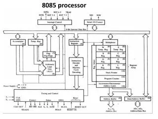
The 8085 and Its Buses The 8085 is an 8-bit general purpose microprocessor that can address 64K Byte of memory. It has 40 pins and uses +5V for power. It can run at a maximum frequency of 3 MHz. The pins on the chip can be grouped into 6 groups: Address Bus. Data Bus. Control and Status Signals. Power supply and frequency. Externally Initiated Signals. Serial I/O ports.
The Address and Data Bus Systems The address bus has 8 signal lines A8 – A15 which are unidirectional. The other 8 address bits are multiplexed (time shared) with the 8 data bits. So, the bits AD0 – AD7 are bi-directional and serve as A0 – A7 and D0 – D7 at the same time. During the execution of the instruction, these lines carry the address bits during the early part, then during the late parts of the execution, they carry the 8 data bits. In order to separate the address from the data, we can use a latch to save the value before the function of the bits changes.
The Control and Status Signals There are 4 main control and status signals. These are: ALE: Address Latch Enable. This signal is a pulse that become 1 when the AD0 – AD7 lines have an address on them. It becomes 0 after that. This signal can be used to enable a latch to save the address bits from the AD lines. RD: Read. Active low. WR: Write. Active low. IO/M: This signal specifies whether the operation is a memory operation (IO/M=0) or an I/O operation (IO/M=1). S1 and S0 : Status signals to specify the kind of operation being performed. Usually not used in small systems.
Frequency Control Signals There are 3 important pins in the frequency control group. X0 and X1 are the inputs from the crystal or clock generating circuit. The frequency is internally divided by 2. So, to run the microprocessor at 3 MHz, a clock running at 6 MHz should be connected to the X0 and X1 pins. CLK (OUT): An output clock pin to drive the clock of the rest of the system. We will discuss the rest of the control signals as we get to them.
A closer look at the 8085 Architecture Now, let’s look at some of its features with more details.
The ALU In addition to the arithmetic & logic circuits, the ALU includes an accumulator, which is a part of every arithmetic & logic operation. Also, the ALU includes a temporary register used for holding data temporarily during the execution of the operation. This temporary register is not accessible by the programmer.
S Z X AC X P X C Flag Register Sign Carry Zero Parity Auxiliary Carry X - Unspecified
The Flags register There is also a flag register whose bits are affected by the arithmetic & logic operations. S-sign flag The sign flag is set if bit D7 of the accumulator is set after an arithmetic or logic operation. Z-zero flag Set if the result of the ALU operation is 0. Otherwise is reset. This flag is affected by operations on the accumulator as well as other registers. (DCR B). AC-Auxiliary Carry This flag is set when a carry is generated from bit D3 and passed to D4 . This flag is used only internally for BCD operations. P-Parity flag After an ALU operation, if the result has an even # of 1s, the p-flag is set. Otherwise it is cleared. So, the flag can be used to indicate even parity. CY-carry flag This flag is set when a carry is generated from bit D7 after an unsigned operation. OV-Overflow flag This flag is set when an overflow occurs after a signed operation.