Download
1 / 23
230 likes | 270 Vues
This video meeting discusses the analysis of quench behavior in TQS technology, including stress, training, and quench locations. Key topics include the use of aluminum shells over iron yokes, low and high pre-stress assembly, and the benefits of reusable structural components.

E N D
TQS Quench Analysis Shlomo Caspi LARP Video Meeting September 22, 2008
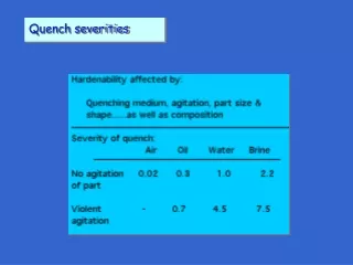
Technology Quadrupole Shell - TQS • Aluminum shell over iron yoke • Assembly with bladders and keys Low pre-stress during assembly High pre-stress with cool-down Reusable structural components 2 CERN, WAMSDO May 2008
Magnet Tests Virgin coils are listed in bold
TQS01 Training • ~10 Q to plateau • TQS01c - 1.9 K • Slow training • ~10% gain
TQS02a Training • TQS02 • 5 Q to plateau • No gain at 1.9 K • Erratic Similar coils - different limiting quenches
Measured TQS Structure Stress • Low assembly stress • Gain during cool-down • Reversible during warm-up
TQS01 – Bronze Poles TQS02 – Titanium Poles Change of Pole Material in TQS02 • Titanium Poles remain in longitudinal compression at all stages • Eliminated stress concentration at pole cuts while reducing axial load • Coil fabrication improvements: - No gaps needed between segments • - Better coil parts fit after reaction • Titanium poles were also adopted for the HD2 and CARE dipoles
Quench Locations 9 TQS01 • Layer 1, straight section, pole turn, near ramp and island gaps • Limit to a single coil same location TQS02 • Layers 1 & 2 pole turn and multi-turns, straight section
4.5K SSL 1.9K SSL TQS01c @ 1.9K 1.9K4.5K (4.5K) TQS01c @ 4.5K Quench current (A) Post-test inspection of pole gaps Quench locations Epoxy tearing TQS01, 01b, 01c Test Results • For all magnets, training started above 70% of the short sample limit • Plateau quenches occur near gaps of pole parts; only one end quench • Plateau quenches in TQS01c follow temperature dependence of Jc
Coil 7 VT B6 VT A8 Coil 6 87% SS Fe FILLER POLE GAP Plateau Quenches in TQS01a, b, c • TQS01 plateau quenches are very repeatable (all segment dV/dt are overlays) • Quench propagation velocity along pole turn can be correlated with local Ic • Calculated “gap” Ic in coil 6 consistent with ~87% quench level (already in Q#4) • TQS01b & TQS01c limit also consistent with Ic degradation (in different coils) SQ02 Measured Quench Velocities Iq/Iss
Calculated bronze pole (TQS01/b/c) Spikes in coil axial strain (cool-down & excitation) Pole gaps Pole gaps Calculated titanium pole (TQS02) Spikes in coil axial strain are reduced/eliminated Coil Stress near Pole Gaps • 3D ANSYS calculations and TQS01b measurements • indicate high longitudinal tension in coil across gaps, • possibly leading to conductor degradation Differential measurements of coil axial strain in TQS01b 3. Training 4. Warm-up 2. Cool-down 1. Assembly
All plateau quenches in coil 21 (coil 20 & 21 participate in the initial training) • Quenches start in the pole turn and the multi-turn segments of the outer layer • Quenches in each of the two plateaus (before/after 1.9K)repeat almost exactly • 1st plateau (21-25): • 2nd plateau (49-54): • Pole turn starts 0.7 ms after multi-turn • Quench fronts also in the inner coil (next to pole & wedges) • pole turn & multi-turn start at the same time • no inner coil quench fronts Quench 25 4.5K Plateau (before 1.9K) Coil 21 Pole Around Lead end Ramp B6A10 Pole turn A10A9 Quenching Sequence ■ 1st ■ 2nd ■ 3rd ■ others Turn 2 A6/7 A5 TQS02a Plateau Quenches (4.5 K)
R&D Issues 14 R&D issues: • Short-sample plateau at 4.4K of 80-90% • Short-sample plateau at 1.9K of 77-84% • Is it only stability at 1.9 K ? • Why different limiting quench currents in similar coils? • Why same quench locations at 4.4K and 1.9K. and why erratic behavior does not move quench location? • We may have lower stability at 1.9K than 4.4K – however could local flaws during coil manufacturing and over-stressing be the main cause of performance limitations both at 4.4K and 1.9K? • Layer 2 quenches in TQS02
Summary • 6 tests – using TQS technology • LARP 200 T/m target – reached 220 T/m • Plans for next 2 tests using TQS02c: • Stability and protection heater studies now underway • Impact of axial pre-stress on magnet performance • Future plan - TQS03: • Improved QA on new coils using 108/127 conductor 15
kA T/m Ramp Rate 1.9 K 2.2K 4.5 K First training cycle at 4.5 K Plateau #1 Plateau #2 200T/m TQS02a Quench Performance TQS02 Test Results • Performed well above 200 T/m at both 4.5 K & 1.9 K; max gradient 224 T/m • First quench >175 T/m; Achieved 200 T/m after two training quenches • Delivered stable performance at 215 T/m(4.5K) after training • Demonstrated RRP 54/61 performance above target gradient (4.5K & 1.9K) • Confirmed the analysis of the cause of the TQS01 limitation and its cure • Training was limited to an average of ~215 T/m at both 4.5 K and 1.9 K • Some scatter/fall backs in the first ~20 quenches at 4.5 K, and at 1.9 K
First 4.5 K plateau (5 quenches) Second 4.5 K plateau (6 quenches) dV/dt (V/s) dV/dt (V/s) OL multi-turn half slope (training) 0.7 ms delay No delay Heater fired OL multi-turn OL pole-turn OL pole-turn (same as 1st plateau) (ms) Time (ms) TQS02 Quench Analysis (4.5K & 1.9K) • Quench origins cannot be precisely located: • However, voltage signal overlays indicate same origin and evolution • Comparison of 1st and 2nd plateau shows further training occurred at 1.9K • At 1.9 K, same limiting coil (#6) and same quench onsets/sequence as 4.5K • Some differences in quench evolution at 1.9K - four identical overlays identified • Some correlation between quench current and dV/dt signatures of each group • Too short extraction delays • Too few V-taps (multi-turn)
TQS02b Training Quench Location • All quenches (4.5K and 1.9K) started in coil 29 at same location (pole turn) • At 1.9K, 20A/s ramps resulted in lower quench current than at 4.5K • At 1.9K, higher ramp rates resulted in higher quench currents • Quench location correlates with cable “kinks” after un-winding/re-winding
TQS02 cool-down Titanium pole Iron filler 200 MPa TQS02 Evaluation and Next Steps • Ti poles removed TQS01 limitation at inner • pole gaps (but increased outer layer stress) • 4.5K plateau: • Quench area is mechanically complex • Different longitudinal strain condition • Possible slipping during unloading • High transverse stress at cool-down • Possible damage in a single coil • 1.9 K behavior: some features may suggest a conductor instability. However: • Slow gain and fall-backs also occurred in the first part of the 4.5K training • Two different mechanisms resulting in same coil, area, dynamics & current? • Overlays of voltage signals would require a very repeatable instability • Short sample measurements show dip, but at ~1.8 times higher current • The same mechanical issues are likely affecting both 4.5K & 1.9K performance • Next step: replace coil 20-21 & (if possible) reduce peak stress in outer layer
TQS02c Test Goals • 1. Improve quench performance by replacing the limiting coil of TQS02b (#29) with coil 20 • Coil 20 was considered a “weak” coil since it participated in the TQS02a quench training; however, it did not limit the magnet (the TQS02a plateau quenches were all in coil 21) • 2. Carry out an extended test in order to perform a deeper analysis of the magnet: • Using quench antennas to longitudinally localize the quenches • Analyzing voltage taps signals, in particular possible quench precursors • Using magnetic measurements to understand the structure behavior during assembly, cool down and powering, and possible modifications of the structure after thermal cycles • Extending magnetic measurements to measure the decay and its dependence on the pre-cycle parameters • 3. Transfer to CERN the knowledge for disassembling and assembling a Nb3Sn magnet in a bladder and key structure. • Disassembly of TQS02b and assembly of TQS02c were carried out at CERN with LBNL participation
TQS02c Quench Origin • All Quenches (4.5K and 1.9K) are in coil 23 B6A10 (ramp between inner and outer layer) • Quench start at 4.5K is at about 110 mm from the V tap A10 with ramp rate of 20A/s • Quench start at 1.9K is at about 210 mm from the V tap A10 with ramp rate of 20A/s • All confirmed by the QA signals • Exceptions: • the beginning of the training for q1-q2 : quenches are in coil 28 • ramp rate >20A/s (4.2K) and ramp rate >140A/s (1.9K): quenches are in coil 23 A2A4 • ramp rate <20A/s (4.2K) when quenches are in coil 23 B4B3 21
TQS Quench Analysis Summary • TQS01 (a,b,c): • Quenches originated at pole gaps, where high axial tension occurred • 3D FEA+SG data guided the change from Bronze to Titanium poles • TQS02 (a,b,c): • New Titanium poles eliminated pole-gap quenches • All models used the same structure and loading conditions • Performance limits in each model are in specific coils/locations: • TQS02a: limited by coil 21 at outer layer pole (both 4.4K & 1.9K) • TQS02b: limited by coil 29 at pole, near end (both 4.4K & 1.9K) • TQS02c: limited by coil 23 at inter-layer ramp (both 4.4K & 1.9K) • All models used the same conductor and heat treat • For TQS02b, weakness could be traced back to coil winding phase • Ramp area limiting TQS02c is also problematic (geometry, handling)
TQS Test Summary • Demonstrated accurate, repeatable control of warm and cold pre-load • Delivered safe, fast assembly and disassembly for all 6 models • Training starts high and improves rapidly to maximum • Reliable structure performance allows to identify conductor/coil issues • Selectively replaced coils to understand limits and improve coil quality • S02 models consistently surpassed the 200 T/m target at 4.4K & 1.9K • Limiting quenches originate at same locations in each model (4.4K & 1.9K) • Limiting quenches originate at different locations for different models • 1.9K limiting quench patterns are not consistent with an intrinsic wire instability • 1.9K limiting quenches are consistent with instability driven by local degradation • TQS02c never quenched below 200 T/m during 4.4K and 1.9K training