Project and PCB making Workshop
Join our comprehensive workshop focused on project design and PCB making. Learn the theory behind compact PCB design, the entire PCB making process, and hands-on skills involved in creating your own electronic circuits. Whether you're using an authorized circuit design or simulating your own, obtain cost-effective components and assemble circuits on breadboards. After testing, you'll create an efficient PCB layout and assemble your circuit onto it. Ideal for enthusiasts looking to enhance their electronics skills for various applications, including digital circuits and remote control.

Project and PCB making Workshop
E N D
Presentation Transcript
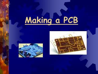
Aim of workshop • Study of theory and to apply it. • To learn, how to design compact PCB. • Learn PCB making process.
Steps involved in making a project. • Take circuit from any authorized source OR design your own circuit using simulators. • Buy components which are to be used in the circuit. Try to buy the components from the shop where they are much cheaper. • Assemble the circuit on breadboard. If the circuit is working properly then proceed to next step. • Make PCB layout for this circuit. PCB layout should be compact, so use datasheets of the components.
Now assemble the circuit on PCB. The steps involved in making PCB will be illustrated later.
Regulated power supply Circuit diagram:
Applications • Most digital IC’s including microprocessors and digital IC’s operate on ±5 volt. • There is often need of clock signal for digital circuits, so 60 Hz square wave is used as a clock signal. Almost all linear IC’s operate on ±15 volt. Hence this power supply is too much useful for electronic projects.
IR Transmitter and Receiver • Circuit diagram (transmitter):
applications • When used with optical fiber, this circuit transmits the signal over large distance. • When used with digital circuit, the above circuit can be used as remote control.