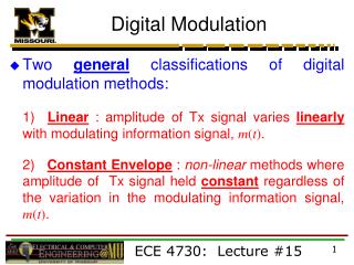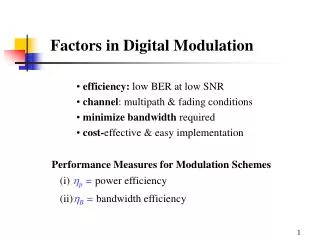
Digital Modulation
Digital Modulation. Lectures. Carrier : A sin[ t + ] A = const = const = const Amplitude modulation (AM) A = A(t) – carries information = const = const. Frequency modulation (FM) A = const = (t) – carries information = const Phase modulation (PM) A = const

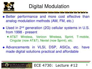
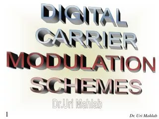
Digital Modulation
E N D
Presentation Transcript
Digital Modulation Lectures
Carrier: A sin[t +] A = const = const = const Amplitude modulation (AM) A = A(t) – carries information = const = const Frequency modulation (FM) A = const = (t)– carries information = const Phase modulation (PM) A = const = const = (t) – carries information Change which part of the Carrier?
Amplitude Shift Keying (ASK) Baseband Data • Pulse shaping can be employed to remove spectral spreading • ASK demonstrates poor performance, as it is heavily affected by noise, fading, and interference 1 0 0 1 0 ASK modulated signal Acos(t) Acos(t)
Frequency Shift Keying (FSK) Baseband Data 1 0 0 1 BFSK modulated signal f0 f0 f1 f1 where f0 =Acos(c-)t and f1 =Acos(c+)t Example: The ITU-T V.21 modem standard uses FSK FSK can be expanded to a M-ary scheme, employing multiple frequencies as different states
Phase Shift Keying (PSK) Baseband Data 1 0 0 1 BPSK modulated signal s0 s0 s1 s1 where s0 =-Acos(ct) and s1 =Acos(ct) Major drawback – rapid amplitude change between symbols due to phase discontinuity, which requires infinite bandwidth. Binary Phase Shift Keying (BPSK) demonstrates better performance than ASK and BFSK BPSK can be expanded to a M-ary scheme, employing multiple phases and amplitudes as different states
Binary Phase Shift Keying (BPSK) If the sinusoidal carrier has an amplitude Ac and energy per bit Eb Then the transmitted BPSK signal is either:
Linear Modulation Techniques: • Digital modulation can be broadly classified as: • Linear (change Amplitude or phase) • Non linear modulation techniques (change frequency). • Linear Modulation Techniques: • The amplitude/phase of the transmitted signal s(t), varies linearly with the modulating digital signal, m(t). • These are bandwidth efficient(because it doesn’t change frequency) and hence are very attractive for use in wireless communication systems where there is an increasing demand to accommodate more and more users within a limited spectrum.
Pros & Cons • Linear Modulation schemes have very good spectral efficiency, • However, they must be transmitted using linear RF amplifiers which have poor power efficiency.
Note • “Phase modulation” can be regarded as “amplitude” modulation because it can really change “envelope”; • Thus both of them belong to “linear modulation”!
Differential Modulation • In the transmitter, each symbol is modulated relative to the previous symbol and modulating signal, for instance in BPSK 0 = no change, 1 = +1800 • In the receiver, the current symbol is demodulated using the previous symbol as a reference. The previous symbol serves as an estimate of the channel. A no-change condition causes the modulated signal to remain at the same 0 or 1 state of the previous symbol.
DPSK • Let {dk} denote the differentially encoded sequence with this added reference bit. We now introduce the following definitions in the generation of this sequence: • If the incoming binary symbol bk is 1, leave the symbol dkunchanged with respect to the previous bit. • If the incoming binary symbol bk is 0, change the symboldk with respect to the previous bit.
DPSK • to send symbol 0, we advance the phase of the current signal waveform by 180 degrees, • to send symbol 1, we leave the phase of the current signal waveform unchanged. • Generation of DPSK: • The differential encoding process at the transmitter input starts with an arbitrary first bit, serving as reference.
Differential Phase Shift Keying (DPSK): • DPSK is a non coherent form of phase shift keying which avoids the need for a coherent reference signal at the receiver. • Advantage: • Non coherent receivers are easy and cheap to build, hence widely used in wireless communications. • DPSK eliminates the need for a coherent reference signal at the receiver by combining two basic operations at the transmitter:
Pulse Carrier • Carrier: A train of identical pulses regularly spaced in time
Pulse-Amplitude Modulation (PAM) • Modulation in which the amplitude of pulses is varied in accordance with the modulating signal. • Used e.g. in telephone switching equipment such as a private branch exchange (PBX)
Pulse-Duration Modulation (PDM) Modulation in which the duration of pulses is varied in accordance with the modulating signal. Deprecated synonyms: pulse-length modulation, pulse-width modulation. Used e.g. in telephone switching equipment such as a private branch exchange (PBX)
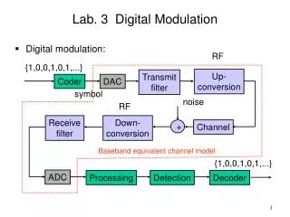
Demodulation & Detection • Demodulation • Is process of removing the carrier signal to obtain the original signal waveform • Detection – extracts the symbols from the waveform • Coherent detection • Non-coherent detection
Coherent Detection • An estimate of the channel phase and attenuation is recovered. It is then possible to reproduce the transmitted signal and demodulate. • Requires a replica carrier wave of the same frequency and phase at the receiver. • Also known as synchronous detection (I.e. carrier recovery)
Coherent Detection 2 • Carrier recovery methods include • Pilot Tone (such as Transparent Tone in Band) • Less power in the information bearing signal, High peak-to-mean power ratio • Carrier recovery from the information signal • E.g. Costas loop • Applicable to • Phase Shift Keying (PSK) • Frequency Shift Keying (FSK) • Amplitude Shift Keying (ASK)
Non-Coherent Detection • Requires no reference wave; does not exploit phase reference information (envelope detection) • Differential Phase Shift Keying (DPSK) • Frequency Shift Keying (FSK) • Amplitude Shift Keying (ASK) • Non coherent detection is less complex than coherent detection (easier to implement), but has worse performance.
QPSK • Quadrature Phase Shift Keying (QPSK) can be interpreted as two independent BPSK systems (one on the I-channel and one on Q-channel), and thus the same performance but twice the bandwidth (spectrum) efficiency.
QPSK Constellation Diagram Q Q • Quadrature Phase Shift Keying has twice the bandwidth efficiency of BPSK since 2 bits are transmitted in a single modulation symbol I I Carrier phases {0, /2, , 3/2} Carrier phases {/4, 3/4, 5/4, 7/4}
Q Q I I Types of QPSK Q • Conventional QPSK has transitions through zero (i.e. 1800 phase transition). Highly linear amplifiers required. • In Offset QPSK, the phase transitions are limited to 900, the transitions on the I and Q channels are staggered. • In /4 QPSK the set of constellation points are toggled each symbol, so transitions through zero cannot occur. This scheme produces the lowest envelope variations. • All QPSK schemes require linear power amplifiers I Conventional QPSK Offset QPSK /4 QPSK
Quadrature Phase Shift Keying (QPSK): • Also a type of linear modulation scheme • Quadrature Phase Shift Keying (QPSK) has twice the bandwidth efficiency of BPSK, since 2 bits are transmitted in a single modulation symbol. • The phase of the carrier takes on 1 of 4 equally spaced values, such as where each value of phase corresponds to a unique pair of message bits. • The QPSK signal for this set of symbol states may be defined as:
QPSK • The striking result is that the bit error probability of QPSK is identical to BPSK, but twice as much data can be sent in the same bandwidth. Thus, when compared to BPSK, QPSK provides twice the spectral efficiency with exactly the same energy efficiency. • Similar to BPSK, QPSK can also be differentially encoded to allow non-coherent detection.
Multi-level (M-ary) Phase and Amplitude Modulation • Amplitude and phase shift keying can be combined to transmit several bits per symbol. • Often referred to as linear as they require linear amplification. • More bandwidth-efficient, but more susceptible to noise. • For M=4, 16QAM has the largest distance between points, but requires very linear amplification. 16PSK has less stringent linearity requirements, but has less spacing between constellation points, and is therefore more affected by noise. 16 QAM 16 PSK 16 APSK
Distortions Perfect channel White noise Phase jitter
Spectral Efficiencies - Examples • GSM Europe Digital Cellular • Data Rate = 270kb/s; Bandwidth = 200kHz • Bandwidth efficiency = 270/200 = 1.35bits/sec/Hz • IS-95 North American Digital Cellular • Data Rate = 48kb/s; Bandwidth = 30kHz • Bandwidth efficiency = 48/30 = 1.6bits/sec/Hz
Minimum Shift Keying (MSK) MSK is a continuous phase-frequency shift keying; Why MSK? -- Exploitation of Phase Information besides frequency.
M-ary Combined Linear and nonlinear (Constant Envelope) Modulation Techniques
Topics : • What is M-ary modulation? • Various M-ary modulation Techniques: M-ary Phase Shift Keying (MPSK) M-ary Quadrature Amplitude Modulation (QAM) M-ary Frequency Shift Keying (MFSK)
Definition: In this modulation Technique the digital data is sent by varying both the envelope and phase(or frequency) of an RF carrier. These modulation techniques map base band data into four or more possible RF carrier signals. Hence, these modulation techniques are called M-ary modulation.
M-ary signaling scheme: • In this signaling scheme 2 or more bits are grouped • together to form a symbol. • One of the M possible signals • s1(t) ,s2(t),s3(t),……sM(t) • is transmitted during each symbol period • of duration Ts. • The number of possible signals = M = 2n, • where n is an integer.
Depending on the variation of amplitude, phase or frequency of the carrier, the modulation scheme is called as M-ary ASK, M-ary PSK and M-ary FSK. Fig: waveforms of (a) ASK (b) PSK (c)FSK
M-ary Phase Shift Keying(MPSK) • In M-ary PSK, the carrier phase takes on one of the M possible values, namely i = 2 * (i - 1) / M where i = 1, 2, 3, …..M. The modulated waveform can be expressed as where Es is energy per symbol = (log2 M) Eb Ts is symbol period = (log2 M) Tb.
The above equation in the Quadrature form is By choosing orthogonal basis signals defined over the interval 0 t Ts