Heating & Cooling Circuit
Heating & Cooling Circuit. OEM Boiler & Burner Equipment Nov 2006. Mixing heating circuit. Y21. Mixing cooling circuit. Mixing cooling circuit with a heat pump. Y21. B9. Y1/Y2. B21. Q9. Q2. RG1. B1. E9. B81. E10. P. P. K1/E11. B83. B71. Y21. B91. Q8/E14.


Heating & Cooling Circuit
E N D
Presentation Transcript
Heating & Cooling Circuit OEM Boiler & Burner EquipmentNov 2006
Y21 Mixing cooling circuit
Mixing cooling circuit with a heat pump Y21 B9 Y1/Y2 B21 Q9 Q2 RG1 B1 E9 B81 E10 P P K1/E11 B83 B71 Y21 B91 Q8/E14
Rh14 B9 HC/CC B9 RG1 Rh38 T T B1 T B16 T CC HC Q2 B1 RG1 T Q24 Y1/Y2 Q2 Y23/Y24 Y21 Y1/Y2 Partial diagram in the zone controller Extension module
Controller with cooling function Heat generation Distribution 2 1 CHP HC Bi- / Multi- valent M 1 2 Constant controller RVA10.121 Boiler RVS13.123 RVS13.143 RVS53.183 RVS43.143 System compatible RVS63.243 System compatible RVS63.283 System compatible Heat pump RVS51.183 RVS61.283 System compatible Zone RVS46.530 System compatible RVS46.543 System compatible
Y21 Y1/Y2 B9 Q2 B1 B2 RG1 K4 Chiller Dehumidifier Boiler/Chiller with heat/cool circuit, 2 pipes Example Italy RVS43.143 AVS75.390
RESET Operating units Cooling button On: cooling function is activatedOff: cooling function is deactivated Heating Heating & Cooling
HMI RU The bar on the display indicates the active operating mode Automatic Reduced Comfort Protection Operating Mode Heating Circuit
Room Temperature Setpoint Heating • TRK Room temperature - Comfort setpoint • TRR Room temperature - Reduced setpoint • TRF Room temperature - frost protection setpoint
Operating Mode Cooling Circuit Cooling button On: cooling function is activatedOff: cooling function is deactivated
Room Temperature Setpoint Cooling • TRK: Room temperature - Comfort setpoint • TRF: Room temperature - frost protection setpoint
Knob for comfort set point HMI RU • Heating mode Set point for room temperature heating e.g. 21°C • Cooling mode Set point for room temperature cooling e.g. 24°C
Functionality The cooling function can be activated any time but it works only if there is no heating demand heating first • Lock time after heating (Par. e.g. 48 hr) • and/ or • Cooling limit at outside temperature Par. e.g. 26°C
Time Switch Program Heating • The nominal phases depend on the settings • made at the enduser level Each time program can be reset separately
Time Switch Program Cooling Release: -24h/day (manual operating) -Time program Heating circuit -Time program 3 -Time program 4/ DHW
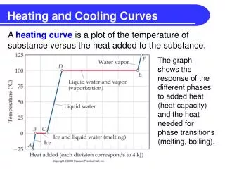
Heating curve – slope TVw TAgem Possibility for heating curve adaptation (optimisation function)
Cooling curve - Flow temp set point at OT 25°C - Flow temp set point at OT 35°C TVKw 0°C Set point25°C Set point35°C TAgem
Flow Temperature Limitation Heating TVw Current flow temperature setpointTVmin Minimum limitation of the flow temperature setpointTVmax Maximum limitation of the flow temperature setpoint
TVKw Flow Temperature Limitation Cooling • Flow temperature minimum limitation -Flow temp set min OT at 25°C • -Flow temp set min OT at 35°C TVKw TVK min Min. limitationSet point 25°C Min. limitationSet point 35°C TAgem
TVKw Flow Temperature Limitation Cooling • Flow temperature minimum limitationDefault setting 18°C (condensing protection) • - Flow temp set min OT at 25°C = 18°C - Flow temp set min OT at 35°C = 18°C TVKw 18°C TVK min Min. limitationSet point 25°C Min. limitationSet point 35°C TAgem
Room Functions for Heating and Cooling Room temperature limitation Room influence must be active (1-100) TRx Actual value of room temperature TRw Room temperature setpoint SDR Room temperature differential P Pump
Room Functions only Heating • Room model • If there is no room sensor connected or room influence is deactivated, the control calculates a virtual room temperature which is used for the following functions: • Boost heating • Quick setback • Optimum start control • Optimum stop control
Room Functions only Heating Room model Calculation depends on: Sth -> gradient room model Tn -> time constant building
Room Functions only Heating Optimum start control The heating‘s switch-on time (change to Comfort temperature) will be selected such that the room temperature will have reached the setpoint minus 0.25 °Cby the time occupancy starts.
Room Functions only Heating Optimum stop control The heating’s switch-off time (change to Reduced temperature) will be selected such that at the time occupancy ends,the room temperature will lie 0.25 °C below the nominal setpoint (early shutdown).
ECO Functions only heating 24-hour heating limit (Tagesheizgrenze) The heating circuit is switched off depending on the actual and the composite outside temperature.
TVKw Control humidity in the room for Cooling • stage • With minimal flow temp set point Set to 18°C B1 sensor required in the flow TVKw 18°C TVK min Min. limitationSet point 25°C Min. limitationSet point 35°C
Control humidity in the room for Cooling 2.stageWith hygrostat in DI H1 (para 5950) Increasing flow temp set point (para 947) TVKw 27 24 Offset (Par) 18°C TVK min Min. limitationSet point 25°C Min. limitationSet point 35°C
Control humidity in the room for Cooling 2.stage or with dew point monitor Switched off the cooling function for a set time (para 946) 3.stage 3 (Step 2) With a humidity sensor Calculating the dew point according the room temperature and the humidity measuring stop
Control humidity in the room for Cooling 3.stage 3 (Step 2) With a humidity sensor Calculating the dew point according the room temperature and the humidity measuring