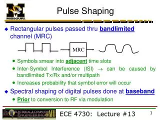
Pulse Shaping with MIIPS
Pulse Shaping with MIIPS. SASS 8/22/2012 David Nicholson. Outline. Pulse shaping introduction MIIPS MATLAB Simulations Actual implementation. Laser pulses can be defined in the time or frequency domains. Electric field of pulse is equivalently defined in both Time: Freq.:

Pulse Shaping with MIIPS
E N D
Presentation Transcript
Pulse Shaping with MIIPS SASS 8/22/2012 David Nicholson
Outline • Pulse shaping introduction • MIIPS • MATLAB Simulations • Actual implementation
Laser pulses can be defined in the time or frequency domains • Electric field of pulse is equivalently defined in both • Time: • Freq.: • Typical fourier transform properties apply
The spectral phase components determine the temporal structure of pulse • Constructive and destructive interference determines temporal profile • As pulse propagates through air and optics, dispersion affects the temporal structure
There are many methods to measure the temporal profile of fs pulses. • FROG • Split beam in two • Cross in SHG crystal and scan time delay • Phase retrieval problem • SPIDER • Split beam in three • Chirp one pulse and cross three in SFG crystal
The 4-f shaper allows the adjustment of spectral phase components. • Once you have measured the phase, a simple way to correct it, or apply any phase is the 4-f shaper • Spectral components modulated in fourier plane by SLM
MIIPS allows for pulse characterization and shaping in a single 4-f device. • Takes advantage of SHG sensitivity to phase profile of input pulse • Place SHG crystal and spectrometer anywhere downstream of 4-f shaper to measure and correct phase at the point SHG Crystal Spectrometer
MIIPS leverages SHG’s dependence on the spectral phase profile.
MIIPS leverages SHG’s dependence on the spectral phase profile.
MIIPS leverages SHG’s dependence on the spectral phase profile.
MIIPS leverages NL signals to measure the input pulse’s phase profile. • Input phase is unknown • Apply reference phase modulation with variable parameter, watch SHG • For each step in parameter variation, maximum SHG signal occurs when curvature of total phase is 0. • Construct 2nd derivative, double integrate to find phase • Apply inverse of phase to correct on SLM
MIIPS iterates on this procedure to find the correct phase to apply. Apply reference phase on top of unknown phase, scan the δ parameter.
MIIPS iterates on this procedure to find the correct phase to apply. The SHG signals are arranged to give the MIIPS trace. Each column is a SHG spectrum reading.
MIIPS iterates on this procedure to find the correct phase to apply. At each frequency, the peak signal is taken to give From this, is generated as:
MIIPS iterates on this procedure to find the correct phase to apply. Knowing that , we integrate to find:
MIIPS iterates on this procedure to find the correct phase to apply. Now start the next iteration, by reapplying the sin modulation.
MIIPS iterates on this procedure to find the correct phase to apply. The SHG signals are arranged to give the MIIPS trace. Each column is a SHG spectrum reading.
MIIPS iterates on this procedure to find the correct phase to apply. At each frequency, the peak signal is taken to give From this, is generated as:
MIIPS iterates on this procedure to find the correct phase to apply. Red curve is correction from this iteration, blue curve is total correction from all iterations Knowing that , we integrate to find:
MIIPS iterates on this procedure to find the correct phase to apply. Now start the next iteration, by reapplying the sin modulation.
MIIPS iterates on this procedure to find the correct phase to apply. The SHG signals are arranged to give the MIIPS trace. Each column is a SHG spectrum reading.
MIIPS iterates on this procedure to find the correct phase to apply.
MIIPS iterates on this procedure to find the correct phase to apply.
MIIPS iterates on this procedure to find the correct phase to apply.
MATLAB simulations demonstrate MIIPS ability to correct unknown phase profiles • MIIPS trace, sin wave scanned over 4π • Time reconstruction of pulse. • Solid red = TL pulse • Dashed red = initial pulse • Blue = pulse after current iteration • Phase profile of pulse • Red = Initial phase profile of pulse • Blue = MIIPS determined phase profile after each iteration
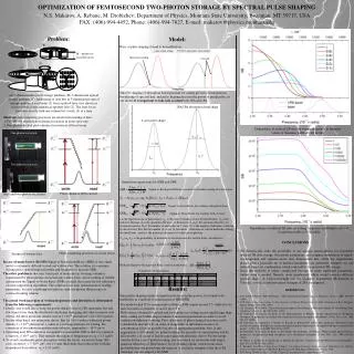
A MIIPS based shaper was built in one of David Reis’s building 40 labs. Actual setup
A MIIPS based shaper was built in one of David Reis’s building 40 lab. • Shaping done between oscillator and regen amplifier • Phase profile maintained through amplifier • SLM is CRi, dual mask 128 pixels • Lens is 6” achromat • Grating is 300 l/mm Coherent Evolution Regen Amp Femtosource Synergy Ti:Sapph Oscillator SLM
A LabVIEW VI was programmed to talk with instruments and do MIIPS
The setup was used to compress the oscillator pulse. • SHG spectrum from OO USB2000 • Temporal profile measured with A.P.E. SPIDER • Dotted red = TL pulse • Blue = temporal profile after each iteration (iteration 0 is pulse with 0 phase applied on SLM) • Spectrum measured with SPIDER • Slight positive quadratic phase from path difference between MIIPS SHG and SPIDER. • Higher order negative phase at wings likely due to low SPIDER signal
There is still room for improvement and work to do. • Switch from lens-based 4f shaper to all reflective • Improve calibration routines for determining applied phase • Increase routine speed • More options in VI • Route the shaped pulse through the Regen amplifier
There are plans to use the pulse shaper for HHG experiments. • SLM allows phase and amplitude shaping • Plan to explore pulse bandwidth and phase profile parameter space to see effect on HHG signals. • Next gen FELs may be HHG-seeded • We hope to gain control over spectral properties of HHG • Linewidthof each harmonic, etc.
Bibliography • V. Lozovoy, I. Pastirk, & M. Dantus. Multiphotonintrapulse interference. IV. Ultrahshort laser pulse spectral phase characterization and compensation. Opt Lett 29, 2004. • I. Pastirk, M. Dantus, et al. No loss spectral phase correction and arbitrary phase shaping of regeneratively amplified femtosecond pulses using MIIPS. Opt Exp 14, 2006. • J. Vaughan. Ultrafast Pulse Shaping. Chapter 13, Ultrafast Optics. (via http://frog.gatech.edu/prose.html) • R. Trebino, et al. Frequency-resolved optical gating with the use of second-harmonic generation. JOSA B 11, 1994. • I. Walmsley, et al. Characterization of sub-6-fs optical pulses with spectral phase interferometry for direct electric-field reconstruction. Opt Lett 24, 1999.