Chapter 2: Protocols and Architecture
COE 341: Data & Computer Communications (Term 061) Dr. Radwan E. Abdel-Aal. Chapter 2: Protocols and Architecture. Agenda. Need for p rotocols and for a layered protocol architecture Key Elements of a Protocol Framework for Standardization Simplified File Transfer Architecture

Chapter 2: Protocols and Architecture
E N D
Presentation Transcript
COE 341: Data & Computer Communications (Term 061)Dr. Radwan E. Abdel-Aal Chapter 2: Protocols and Architecture
Agenda • Need for protocols and for a layered protocol architecture • Key Elements of a Protocol • Framework for Standardization • Simplified File Transfer Architecture • A Three-Layer Model • Protocol Architectures and Networks: Addressing • Primitives and Parameters • Protocol operation: Protocol Data Units (PDUs) • Standard Protocol Architectures • The OSI Protocol Architecture • The Model • OSI Layers • The OSI versus the TCP/IP (the Internet) Protocol Architecture
What is a Protocol? • A set of rules or conventions agreed upon and observed by two communicating entities for successful exchange of data
Why we Need Protocols? • Equipment come from different vendors and run different operating systems… Need common standard procedures and language to communicate properly • Example: File transfer • Source must: • Activate communications link • Check if destination is prepared to receive data • Source file transfer application must: • Check if destination file management system will accept and can store file • May need file format translation, etc…
Why we need Architecture (hierarchy) for Protocols? High Level, e.g. Applications • A large task is better handled through splitting it into smaller subtasks (divide & Conquer) • Can be developed simultaneously by different teams using different platforms (hardware, software) • Hierarchicallayered architecture: • The subtasks are implemented separately in layers forming a stack • The stack is implemented in all communicating end systems • Higher layers handle higher-level tasks • A layer provides/requests services to/from an adjacent layer on a system • Peer layers in the two communicating systems interact with each other using a protocol • Examples from everyday life Low Level, e.g. Signals, Bits
Guidelines for layering • Each layer performs a subset of related subtasks • Each layer provides services to the higher layer and requests services from the lower layer • Ideally, changes in one layer should not require changes to other layers, e.g. changing the link from wire to optical fibre should require changing only the physical layer • Information hiding: Each layer sees only what it needs to see • Not too few layers: • Not enough splitting of functionality • Not too many layers: • Difficult to manage • Large communication overhead between them Physical Link
Protocol Architecture: Layered Structure High-level functions Communicating Entity By exchanging formatted data blocks that obey a protocol: (PDUs) Services Provided Services Requested Highest Level Communication with peer layers on other entities Lowest Level Most primitive functions Physical Link Protocol stack on an end system
Framework for Standardization Well-defined interfaces at layer boundaries Standards/code for various layers can be developed Independently, Simultaneously, Using different platforms (Advantage) Requests From/To Services To/From Changes and upgrades in a layer need not affect other layers WK 2
Scope for Standardization at the Layers • Service Definitions: • State onlyas a functional description- not how to implement it (for flexibility) • For internal use only within this communicating entity (not a protocol) (at the layer interfaces) 2 SAP # 2 … SAP # 1 Here we are dealing with other (foreign) systems! Need a strict protocol Addressing within the same system: Services are requested from /provided by a layer through Service Access Points (SAPs) (or Ports). Use the SAP (port) number for addressing 1 3
So, three standardization elements: • Addressing within the same system • Referencing by SAP numbers: We name the entity in a layer requesting a service from a lower layer by the SAP used on that lower layer • Service definitions (vertically within a system) • Only Functional description of what is required between layers within the same system • Protocol specification (Horizontally, more strict) • Operates between the same layer on the two communicating entities (peer layers) • May involve different operating systems • So, protocol specifications must be defined precisely • Format of data units • Semantics (meanings) of all fields
Example: Simplified Protocol Architecture • The task of file transfer is broken down into three modules (layers) that handle: • File transfer application Application layer (Top) • Communication services Transport layer • Network access Network access layer
Simplified Architecture for File Transfer A Three-Layer Model End System Peer layers on the two systems communicate using Protocols End System Services Requested/ Provided On the same system
Network Access Layer • Function: Exchange of data between a computer and the network • Depends on type of network used (LAN, packet switched, etc.) (should be the only layer that worries about such details) • Should specify: • Address of destination computer on the network • Possibly the level of service required from the network, e.g. priority, delay, etc.
Transport Layer (communication services) • Function:Reliable exchange of data (error and flow etc.) • Independent of network used (significance) • Independent of application (serves all the higher-level applications- sharing of resources)
Application Layer • Function: Supports different user applications running on the communicating entity: e.g. e-mail, file transfer, etc.
Protocol Architecture and Networks Applications Layer:contains modules, each supporting an application running on this computer (SAP) Each application accesses the services of the transport layer through a SAP or a Port 3 computers communicating over a network Using a 3-layer protocol architecture
Addressing Requirements • Two levels of addressing: • Each computer on the network needs a unique computer address • Each application on a (multi-tasking) computer needs a unique application addresswithin that computer • We identify the application on a computer by the SAP number it uses: • “Service access point or SAP” in OSI, e.g. SAP 3 • “Port” in TCP/IP, e.g. Port 5 • Each of the two addressing levels is handled only by the appropriate layer (information hiding): • Computer address is handled by the Network Access layer • Application address (SAP #) is handled by the Transport layer Example: KFUPM mail bag
Protocol Data Units (PDU) Peer layers communicate (through the lower layers of course!) by exchanging PDU data blocks At source: Each layer adds its relevant control information (header) to the data it receives from a higher layer, thus forming its PDU, and pushes it down to the lower layer: Encapsulation At destination: that PDU is handled by the corresponding peer layer: The relevant control header is removed, used, and the remaining part of the PDU is pushed up to the higher layer: Decapsulation Example: • Transport layer may fragment user data into smaller packets • A transport header is appended to each packet, which would include: • Destination SAP • Sequence number of the data fragment • Possibly, error detection/correction code • This makes the transport layer protocol data unit(PDU) Example: The mail service
Protocol Data Units (PDUs) Application Layer User Data Transport Layer What to include in the header? • Address of destination application on the destination computer • Packet sequence # • Error detection code? Network Access Layer • Address of destination computer on the network • Network facilities required, e.g. delay Network
Generating PDUs at Source layers . . . • Layer L generates its PDU by appending a control part to data received from the next higher layer (L+1) • Appended control part takes the form of a header • That header will be used by the peer layer L on the destination entity • Both the new PDU and header are labeled (identified) by the layer generating/using them, i.e. Header (L) + PDU (L+1) PDU (L) Lower Layers L+1 L . . . Source End System
Operation of a Protocol Architecture User Data Destination SAP TFER (record, DSAP, Dhost) Destination Host PDU Decapsulation PDU Encapsulation (Transport PDU) TFER (transport_PDU, Dhost) Network (Network Access PDU) Concept of “overhead”
Standardizing Vertical Communication: Service Primitives and Parameters • Services between vertically adjacent layers within the same system are expressed in terms of primitives and parameters • Primitives specify the action to be performed • Parameters pass data and control information required to perform the action • Services are requested by a service userlayer • … andperformed by a service providerlayer TFER (record, DSAP, Dhost)
Source (X) Destination (Y) Types of Primitives D: Service User A: Service User 2 3 1 4 C: Service Provider B: Service Provider Time Sequence: A to B: “Deliver this packet to Y” 1 C to D: “Here is a packet for you!” 2 D to C: “Thanks!” 3 B to A: “Done it!” 4 Which pair of primitives is more important?
Timing Sequence for Service Primitives Destination System Destination System Source System Source System Provider Provider Provider Provider A D B C No Response or Confirm (Assumed Done!) Saves time…
Standardized Protocol Architectures • Required to allow devices from different manufacturers to communicate (inter-operability) • A win-win environment: • Helps different vendors market their products better • Helps customers shop around for best deals from different manufacturers (assured that equipment will work together) • Main standard networking architectures: • OSI Reference model (X.200, 1977) • A theoretical system delivered too late! Never lived up to early promises • TCP/IP protocol suite (Developed for early forms of the internet) • (The Internet protocol) Most widely used: Ade facto Standard
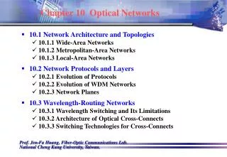
OSI - The Model • Developed by the International Standardization Organization (ISO) in 1977 • A 7-layer model • Each layer: • performs a subset of the required communication functions • relies on the next lower layer to perform more primitive functions • provides services to the next higher layer • Changes in one layer should not require changes in other layers
The OSI Seven Layers Internetworking (network of networks) (Internet) End to End Virtual Connection The Physical Medium
The OSI Environment Encapsulation Decapsulation Hardware or software Trailer Marking end of frame Note information hiding! e.g. DL layer does not“look inside” the N-DPU
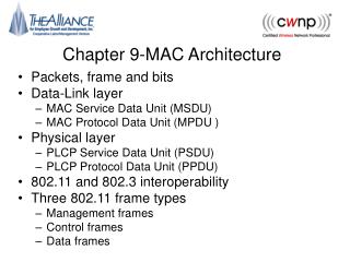
OSI Layers with examples (1) • Physical Example: 10Base-T for Ethernet LAN Physical interface between devices • Mechanical: Connectors, etc. • Electrical: Bit representation, V and I levels, Data rates,... • Functional: Functions of individual interface circuits • Procedural: Sequence of events for exchanging bit streams • Data Link Example: HDLC (High level data link control) (Ch 7) • Activating, maintaining and deactivating the data link (link management): • Reliable data transfer across the link: synchronization, error detection and control, flow control, so that higher layers may assume error free transmission over the link
OSI Layers with examples (2) • Network Example: X.25 (Packet switching network) • Data transportation over a network • Relieves higher layers from worrying about underlying network details (routing, switching technology, etc) • Only needs info on destination host address and required facilities • Not needed (bypassed) on direct (point-to-point) connections • Transport Example: TCP (Transmission Control Protocol) • Reliable exchange of data between end systems: (possibly across multiple networks!) • Without errors • Without loss • Without duplication • Allows different levels of Quality of Service (QoS): Regarding acceptable error rates, maximum delay, priority, and security
OSI Layers (3) • Session Control of dialogues between applications running on end systems • Dialogue disciplines, e.g. full duplex or half duplex • Grouping: Marking of data to indicate different groups • Recovery: Use of data check points • Presentation • Data formats and coding • Data compression • Data Encryption • Application • Allows user applications running on a host to access the OSI network environment • Support for e-mail, file transfer, terminal access to remote computers (telnet), etc.
Do we always need all the seven protocol layers? • Only hosts at end points need to have all 7 layers • Point-to-Point on a single link: - Network layer is bypassed • Intermediate nodes in network are not interested in user data!- - Will have only the minimum number of required lower layers: • Within the same network: An intermediate node needs only the bottom 3 layers (3-layer switch) • Between multiple networks: A node linking two networks (router) needs only the bottom … layers
Layers for a Relay node in a network A 3-Layer node (Network node) ? • Relay Node, Joins: • Different physical links • Different data links • In the same network What about a router that connects two networks? (Intermediate Network node is not interested in the data content- so, only the lower layers)
TCP/IP Protocol Architecture • Developed by the US Defense Advanced Research Project Agency (DARPA) for its packet switched network ARPANET (ancestor of the present Internet, 1966) • Used today by the Internet • Did not start as a formal model.. but as a working one • Five Layers: • Application layer • Host to host (end to end) Transport layer • Internet layer (multiple interconnected networks) • Network access layer (Data link/Network) • Physical layer = Same layer exists also in OSI
Summary (Chapter 2) • Need for protocols and for a layered protocol architecture • Key Elements of a Protocol • Framework for Standardization • Simplified File Transfer Architecture • A Three-Layer Model • Protocol Architectures and Networks: Addressing • Primitives and Parameters • Protocol operation: PDUs • Standard Protocol Architectures • The OSI Protocol Architecture • The Model • OSI Layers • The OSI versus the TCP/IP (the Internet) Protocol Architecture)