Timers and Low Power Modes
380 likes | 650 Vues
Timers and Low Power Modes. Presented by IEEE of Texas A&M. About This Workshop. Based on the MSP430G2553 microcontroller by Texas Instruments Powerpoint and code available at ieeetamu.org/mcc/ timersLPM Workshop Reference available at ieeetamu.org/mcc/ wsref

Timers and Low Power Modes
E N D
Presentation Transcript
Timers and Low Power Modes Presented by IEEE of Texas A&M
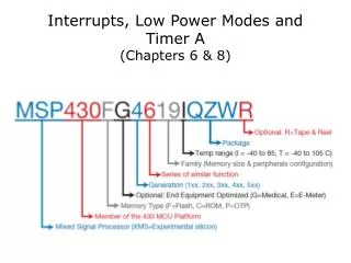
About This Workshop • Based on the MSP430G2553 microcontroller by Texas Instruments • Powerpoint and code available at ieeetamu.org/mcc/timersLPM • Workshop Reference available at ieeetamu.org/mcc/wsref • Footnotes refer to User Guide (UG), Datasheet, or Workshop Reference (WSRef)
Import code projects into Code Composer • Follow instructions in the Workshop Reference or at ieeetamu.org/mcc/importing • Code: ieeetamu.org/mcc/timersLPM • Projects to import: • Longest 16 Bit Timer • 32 Bit Timer • PWM
Extremely Useful Documents • User's Guide – MSP430x2xx Family • http://www.ti.com/lit/ug/slau144i/slau144i.pdf • All general MSP430 information • Ex: MSP430 Architecture, Instruction Set, Registers, clocks, timers, module types and functionality • MSP430G2x53 Datasheet • http://www.ti.com/lit/ds/slas735g/slas735g.pdf • Information specific to individual set of chips • Ex: List of included modules, pin-outs, memory size
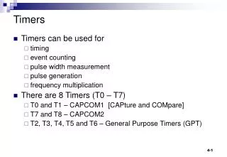
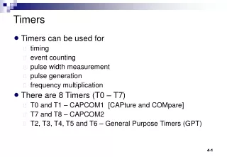
Topics • Introduction to Timers • 16 Bit Timers • 32 Bit Timers • Low Power Modes • Pulse Width Modulation
Timers • Timers keep count of things • They can be used to plan out tasks • Ex. Count to 30, then execute a task. • Simple right? not exactly. • We are limited to 16 bit timers • 16 bit - only counts up to 216 • Can emulate a 32+ bit timer using software • 32 bit - only count up to 232
Types of Timers • Continuous Timers • Counting up Timers • Up-Down Timers • All types are available for Timer A0 and A1 • All can be used as a real time timer
Continuous Timers • Counts up to the max value (0xFFFF, 65535) every time • Max value is always 0xFFFF
Counting Up Timer • Counts up to a certain value (TACCR0) then repeats • Almost identical to a continuous timer • Always increasing or “counting up”
Up – Down Timers • Counts up to a value (TACCR0) and then counts down back to zero • Goes both up and down
MSP430 Clock Sources for Timers • MCLK – Master Clock • Can’t be used as source • Used by the CPU and system • SMCLK – Sub-System Master clock • ACLK – Auxiliary clock • DCO – Digitally controlled oscillator • Can’t be used as source
Timer/Clock Resolution • We can trigger an interrupt at a certain time • We can use the 16 bit timer or increase the maximum value using a variable to emulate a 32 bit timer • We can use the 32 bit when the 16 bit doesn’t suffice
TACTL - Timer A Control Register • CCR0 - The capture compare register compare its value with the timer. Divider for the input clock Timer Modes Clock Source Select Section 12.3.1 in the MSP430x2xx user guide (Page 378)
TACTL - Timer A Control Register • Timer A (TACTL) • Consists of • The Timer A clock source (TASSELx) • These bits select the divider for the input clock (IDx) • Clock mode control (MCx) Section 12.3.1 in the MSP430x2xx user guide (Page 378)
TACTL - Timer A Control Register • The Timer A clock source (TASSELx) • TACLK (TASSEL_0) • ACLK (TASSEL_1) • SMCLK (TASSEL_2) • INCLK (TASSEL_3) Section 12.3.1 in the MSP430x2xx user guide (Page 378)
TACTL - Timer A Control Register • These bits select the divider for the input clock (IDx) • (ID_0) is divide by 1 • (ID_1) is divide by 2 • (ID_2) is divide by 4 • (ID_3) is divide by 8 Section 12.3.1 in the MSP430x2xx user guide (Page 378)
TACTL - Timer A Control Register • Clock mode control (MC_1) • (MC_0) Stop mode: the timer halts • (MC_1) Up mode: the timer counts up CCR0 • (MC_2) Continuous mode: the timer counts up to the max value of CCR0 • (MC_3) Up down mode: the timer counts up CCR0 and then down to 0x0000h Section 12.3.1 in the MSP430x2xx user guide (Page 378)
16 Bit Timer Code • Now open the project for 16 bit timer • Then run the code void main(void) { WDTCTL = WDTPW + WDTHOLD; // Stop WDT P1DIR |= GREEN_LED + RED_LED; // P1.0 output CCTL0 = CCIE; // CCR0 interrupt enabled CCR0 = 0xFFFF; // max value for 16 bit timer TACTL = TASSEL_2 + MC_1 + ID_3; _BIS_SR(LPM0_bits + GIE); // Enter LPM0 w/interrupt } #pragmavector=TIMER0_A0_VECTOR __interruptvoidTimer_A (void) { P1OUT ^= RED_LED; // Toggle P1.0 }
Exercise: 16 Bit Timer Code 1. Change the hex value for CCTL0 2. Change the ID value 3. Change the timer mode or timer select voidmain(void) { WDTCTL = WDTPW + WDTHOLD; // Stop WDT P1DIR |= (GREEN_LED + RED_LED); // P1.0 output CCTL0 = CCIE; // CCR0 interrupt enabled CCR0 = 0xFFFF; TACTL = TASSEL_2+ MC_1+ ID_3; _BIS_SR(LPM0_bits + GIE); // Enter LPM0 w/interrupt } #pragmavector=TIMER0_A0_VECTOR __interruptvoidTimer_A (void) { P1OUT ^= RED_LED; // Toggle P1.0 }
32 Bit Timer Code • Now open the project for 32 bit timer and close the 16 bit timer. • Then run the code unsignedint timer_32_flag = 0; void main(void) { WDTCTL = WDTPW + WDTHOLD; // Stop WDT P1DIR |= (GREEN_LED + RED_LED); // Green and Red led output CCTL0 = CCIE; // CCR0 interrupt enabled CCR0 = 0xFFFF; // value that the timer counts up to TACTL = TASSEL_2 + MC_1 + ID_3 _BIS_SR(LPM0_bits + GIE); // Enter LPM0 w/ interrupt. } #pragmavector=TIMER0_A0_VECTOR // Timer A0 interrupt service routine __interruptvoidTimer_A (void) { timer_32_flag++; // counts the number of times that we have reached the 16 bit timer if(timer_32_flag > 3) { P1OUT ^= RED_LED; // Toggle the Red LED timer_32_flag = 0; // Reset the flag } }
Exercise: 32 Bit Timer 1. Now change the CCR0 value 2. Change the ID_3 to another IDx value 3. Change the timer mode or timer select voidmain(void) { WDTCTL = WDTPW + WDTHOLD; P1DIR |= (GREEN_LED + RED_LED); CCTL0 = CCIE; CCR0 = 0xFFFF; TACTL = TASSEL_2+ MC_1+ ID_3; _BIS_SR(LPM0_bits + GIE); }
Exercise: 32 Bit Timer 4. Change the value the flag can go up to #pragmavector=TIMER0_A0_VECTOR __interruptvoidTimer_A (void) { //counts times interrupt has triggered timer_32_flag++; if(timer_32_flag > 3) { P1OUT ^=RED_LED; // Toggle the Red LED timer_32_flag = 0; } }
Low Power Modes • Allows you to scale power usage of the microcontroller • Why? You can shut off parts of the MSP430 that you aren’t using.
6Types of Low Power Modes • AM – All clocks are active • LPM0 - The CPU is disabled and MCLK is disabled. • LPM1 - The DCO’s generator is disabled. • LPM2 – SMCLK is also disabled. • LPM3 – Same as LPM2. Don’t know why this was added. • LPM4 – The ACLK and the crystal oscillator are also disabled. • NOTE: As Low Power mode rises, all previous low power modes are also included • (Ex. LPM3 includes LPM0-LPM2)
Exercise: Sleep Mode on 32 bit Timer • LPM0_bits turns off the CPU • GIE allows general interrupts • What happens in our code when the low power mode changes? voidmain(void) { WDTCTL = WDTPW + WDTHOLD; P1DIR |= (GREEN_LED + RED_LED); CCTL0 = CCIE; CCR0 = 0xFFFF; TACTL = TASSEL_2 + MC_1 + ID_3; _BIS_SR(LPM0_bits + GIE); }
PWM • Controls the percentage of time the wave is high across one period • The device will see the average voltage • Ex. If the duty cycle is less, an LED will look dimmer • Ex. A motor at certain speeds Average Voltage
PWM: Duty Cycles CCR0 CCR1 Timer ON OFF PWM Signal
PWM: Duty Cycles CCR0 CCR1 Timer ON OFF PWM Signal
PWM Code • Now open the project for PWM and close the 32 bit timer. • Then run the code voidmain(void) { WDTCTL = WDTPW + WDTHOLD; // Stop WDT P1DIR |= GREEN_LED; // P1.6 output P1SEL |= GREEN_LED; // P1.6 TA0.1 options CCR0 = 0xFFFF-2; // PWM Period CCTL1 = OUTMOD_7; // CCR1 reset/set CCR1 = 0x8000; // CCR1 PWM duty cycle TACTL = TASSEL_2 + MC_1; // SMCLK, up mode _BIS_SR(LPM0_bits); // Enter LPM0 }
PWM Code: Out Modes • Out Modes • OUTMOD_0 • OUTMOD_1 • OUTMOD_2 • OUTMOD_3: The output is set when the timer counts to the TACCRx value. It is reset when the timer counts to the TACCR0 value • OUTMOD_4 • OUTMOD_5 • OUTMOD_6 • OUTMOD_7: The output is reset when the timer counts to the TACCRx value. It is set when the timer counts to the TACCR0 value. • Only worry about OUTMOD_3 and OUTMOD_7
Exercise: PWM Code • Change the PWM duty cycle • Change the OUTMOD voidmain(void) { WDTCTL = WDTPW + WDTHOLD; // Stop WDT P1DIR |= GREEN_LED; // P1.6 output P1SEL |= GREEN_LED; // P1.6 TA0.1 options CCR0 = 0xFFFF; // PWM Period CCTL1 = OUTMOD_7; // CCR1 reset/set CCR1 = 0x8000; // CCR1 PWM duty cycle TACTL = TASSEL_2 + MC_1; // SMCLK, up mode _BIS_SR(LPM0_bits); // Enter LPM0 }