Download

1 / 22
230 likes | 386 Vues
This guide explores the functionality of timers and interrupts within AVR microcontrollers, essential for efficient programming and system control. We detail how to interface a 16x2 LCD for displaying outputs, the role of TSOP sensors for infrared detection, and ways to generate 38 kHz signals. Delve into the various timer modes including Normal, CTC, and PWM, while learning how interrupts can streamline processes by allowing event-driven programming. Whether for debugging or sensor calibration, mastering these concepts is crucial for effective microcontroller applications.

E N D
Timers and Interrupts Shivendu Bhushan Sonu Agarwal
Software needed AVR STUDIO CVAVR Extreme Burner AVR
Character LCD • We interface an LCD to our microcontroller so that we can display messages, outputs, etc. • Sometimes using an LCD becomes almost inevitable for debugging and calibrating the sensors • We will use the 16x2 LCD, which means it has two rows of 16 characters each. Hence in total we can display 32 characters
Just Think Over! TSOP sensor detects the presence of light from the Infrared LED How will it distinguish from other Infrared light already present Should we use some kind of encoding ? TSOP sensor detects Infrared light only at 38 KHz How do we generate waves at 38KHz? Timers and Interrupts…
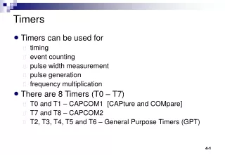
Timers 8-bit register. Values starts from 0 and goes up to 255. Timer value increases by 1,after each period. When the timer reaches its maximum value, in the next cycle, its value becomes 0 again and the process repeats itself. The timer frequency can be factors of the base frequency of the MCU. This process is independent of the CPU.
Simple Statistics • Maximum value of timer is n and clock period is t, then: 1. Timer period = t 2. Timer cycle period = (𝑛+1)×𝑡 3. Frequency of timer (f) = 1/𝑡 4. Frequency of timer cycle = 1/(𝑛+1)×𝑡
Timer Modes A timer works in three modes: Normal, CTC and PWM Normal mode: Timer starts at zero, goes to maximum value and then resets itself CTC (Clear Timer on Compare), clearly the timer starts at zero as usual, but instead of resetting after maximum value, it resets after reaching value specified in OCR register PWM(Pulse Width Modulation) can be used to obtain analog values at the pins
Suppose you need to check for a condition A while running another condition B -> Suppose Event A happens here while(1){ ---- -> if (Event A == true) ---- -> // print event A has occurred ---- ---- ---- -> Event B ---- ---- } Do you see the problem in this approach??
A better Solution: Interrupt • Interrupts means causing a break in a continuing process. • We execute the Event B in a normal while(1) loop. . while(1){ --- --- EVENT B --- --- } . • We will consider the occurrence of event A as an interrupt
Interrupts // print event A has occurred We execute the required code in handler of event A . while(1){ --- --- EVENT B --- --- } . handleA(){ . --- }
More on Interrupts • Interrupts are special events that can “interrupt” the normal flow of a program. • Whenever an Interrupt is called, the processor stops the normal program, handles the interrupt, and then resumes its normal work. • There are two types of interrupts: • External • Internal
External Interrupts The controller monitors the input at the special pins INT0 and INT1, whenever external interrupt is set on. We can configure the program to call an external interrupt whenever any of the following conditions are met. Rising Edge Falling Edge Any change Low level
Internal Interrupts The internal interrupts are called when different specific conditions are met by the timer value. Timers can generate certain interrupts: two, to be precise. These are called OVERFLOW interrupt and COMPARE MATCH interrupt.
Overflow interrupts An overflow interrupt is generated when the timer exceeds its maximum value and resets to 0. The interrupt may or may not have a handler. In either case, the timer continues to run; remember: timers are independent of the CPU. Suppose a timer of maximum value n has a time period t (also called as clock period). Then : 1. Timer cycle frequency = 1/(𝑛+1)×𝑡 2. OVERFLOW interrupt frequency = 1/(𝑛+1)×𝑡 If OVERFLOW interrupt is enabled, then an interrupt is generated in every cycle.
Compare Match Interrupt A compare match interrupt is called when the value of the timer equals a specific value, set by the user. This value is set by setting the value of OCR register. Before incrementing, the value of the timer is compared to OCR. If the two are equal, a COMPARE MATCH interrupt is generated. Suppose a timer of maximum value n has a time period t (also called as clock period). Then : 1. Timer cycle frequency = 1/(𝑛+1)×𝑡 2. COMPARE MATCH interrupt frequency = 1/(𝑛+1)×𝑡 If COMPARE MATCH interrupt is enabled, then an interrupt is generated in every cycle.
Timers and Interrupts All three timer modes differ in the response of the controller to the interrupts generated OVERFLOW and COMPARE MATCH interrupts generated as normal in NORMAL timer mode Compare match interrupt if enabled will be generated but not overflow interrupt (Why?)
Workshop next week after Spectrum! Will send a Google doc for slots Till then go through the slides.. Discuss with your friends.. Start looking for your team This time magnitude of the competition is going to be high This time along with learning, you get a hefty prize money ;)
Thanks Website : http://students.iitk.ac.in/eclub/index.php FB Group : https://www.facebook.com/groups/eclub.iitk/ E-mail : eclub.iitk@gmail.com Youtube : http://www.youtube.com/user/electronicsclub